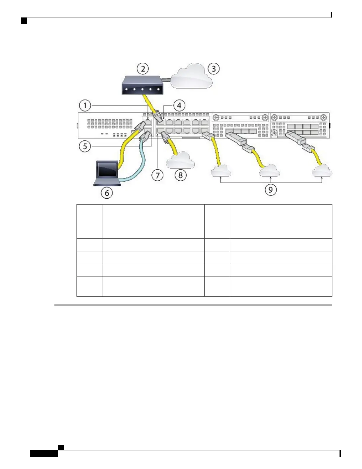
Figure 45: Connect Cables to Firepower 2100 Interfaces
WAN modem2Management 1/1 (management port)
FXOS: 192.168.45.45
ASA: 192.168.45.1
1
Ethernet 1/1 (outside, DHCP from modem)4Internet3
Management computer (DHCP)6Console port (for optional CLI access)5
Inside8Ethernet 1/2 (inside 192.168.1.1)7
Other data networks (SFP/SFP+
transceivers)
9
Step 1 Connect your management computer using Ethernet to Management 1/1.
Step 2 (Optional) Connect your management computer to the console port. The Firepower 2100 ships with a DB-9 to RJ-45
serial cable, so you will need a third-party serial-to-USB cable to make the connection. Be sure to install any necessary
USB serial drivers for your operating system.
Step 3 Connect the outside network to the Ethernet 1/1 port (labeled WAN). For Smart Software Licensing, the ASA needs
internet access so that it can access the License Authority.
Step 4 Connect the inside network to Ethernet 1/2.
Step 5 Connect other data interfaces as needed using SFP/SFP+ transceivers. Install SFP/SFP+/ transceivers in the Ethernet
network interfaces in the 4 fixed ports or in the network module (Firepower 2130/2140 only) taking care not to touch
the contacts in the rear.
Do not force an SFP transceiver into a socket. This can jam the transceiver and can cause permanent damage
to the transceiver, the chassis, or both.
Warning
Cisco Firepower 2100 Series Hardware Installation Guide
64
Mount and Connect
Connect Cables, Turn on Power, and Verify Connectivity for Cisco ASA
 Loading...


