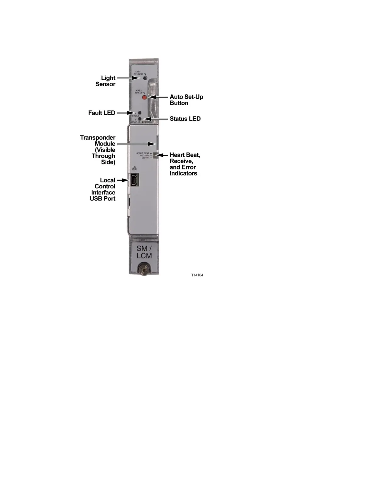
Note: The transponder core module can be seen through the Heart
Beat/Receive/Error indicator cutout in the cover.
Local Control Module Description
The local control module locally monitors the following node voltages and signals:
Receiver optical input level (all receivers)
Transmitter optical output level (all transmitters)
AC power presence and peak voltage (for split AC powering cases, AC
power from both sides of node housing is monitored)
DC voltages from both primary and redundant power supplies
Optical amplifier operating parameters
Optical switch operating parameters
The local control module communicates serially with the RF amplifier module to
control the optional forward band redundancy switches on the forward