Chapter 2 Theory of Operation
configuration module. It is a low-cost module that plugs into the status monitor
connectors on the optical interface board.
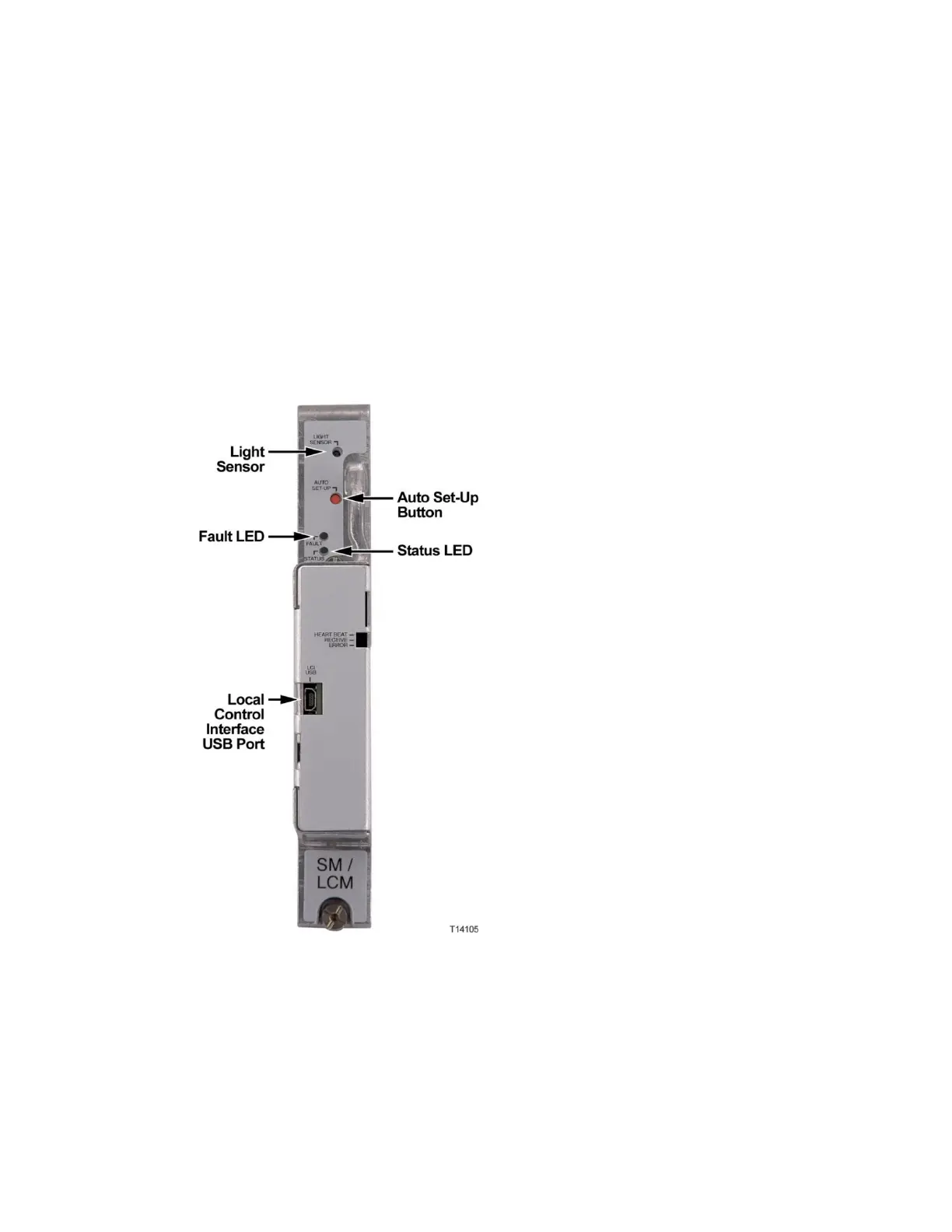
The local control module is equipped with a USB port to allow local control of the
optional forward band redundancy switches, the reverse band 6 dB (wink)
attenuators, the reverse band on/off switches, the optical switch, and optical
amplifiers through the PC-based GS7000 ViewPort software. All parameters
monitored by the local control module can be displayed and reviewed using
ViewPort.
Note: The local control module can be upgraded to a status monitor through the
addition of a transponder core module. The transponder core module plugs directly
onto the local control module’s PWB. The mechanical housing for the status monitor
and the local control module are the same. The Heart Beat, Receive, and Error
indicator LEDs are only present if the transponder module is installed.