2-6
Cisco IR800 Integrated Services Router Software Configuration Guide
Chapter 2 Product Overview
Hardware Overview
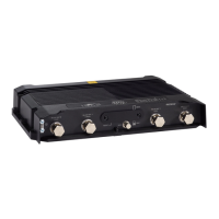
Figure 2-5 shows the back panels details of the Cisco IR829 Dual Modem.
Figure 2-5 Cisco IR829 Back Panel Dual Modem
Note Behind the SIM Door Assembly, there is a reset switch (1), Mini USB console port (2), and Dual SIM
slots (3). See Figure 2-6 for details
1 WLAN ANT 0 5GHz 5 Denotes SIM card order, SIM0 on top and
SIM1 on bottom.
2 WLAN ANT 1 2.4GHz 6 WLAN ANT 1 5GHz
3 Cover over SIM cards, reset button and
console port cover, see Figure 2-6
7 CELLULAR 0 MAIN
4 GPS SMA
1 Cellular 1 Main 5 Denotes SIM card order, SIM0 on top and
SIM1 on bottom.
2 WLAN ANT 1 2.4/5GHz 6 Cellular 1 AUX
3 Cover over SIM cards, reset button and
console port cover, see Figure 2-6
7 CELLULAR 0 MAIN
4 GPS SMA
 Loading...