2-9
Cisco IR800 Integrated Services Router Software Configuration Guide
Chapter 2 Product Overview
Hardware Overview
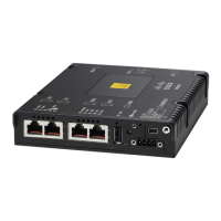
Figure 2-10 Cisco IR809 Front Panel
Note LEDs are viewable from the top and from the front of the IR809.
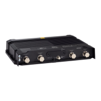
Figure 2-4 shows the back panels details of the Cisco IR809.
1 S0 RS232 DCE/RS485 Combo Port 8 Grounding Point
2 S1 RS232 DTE only 9 Mini type-B USB console/debug port
3 GE0 (10/100/1000) 10 SYS LED
4 GE1 (10/100/1000) 11 Alarm LED
5 USB 2.0 (Type-A Host Port) 12 WAN/WWAN LEDs
6 RESET Button 13 SIM Card LEDs
7 DC Power/Alarm Connector
 Loading...