3-37
Cisco ISA 3000 Industrial Security Appliance Hardware Installation Guide
Chapter 3 Connecting the ISA 3000
Connecting to DC Power
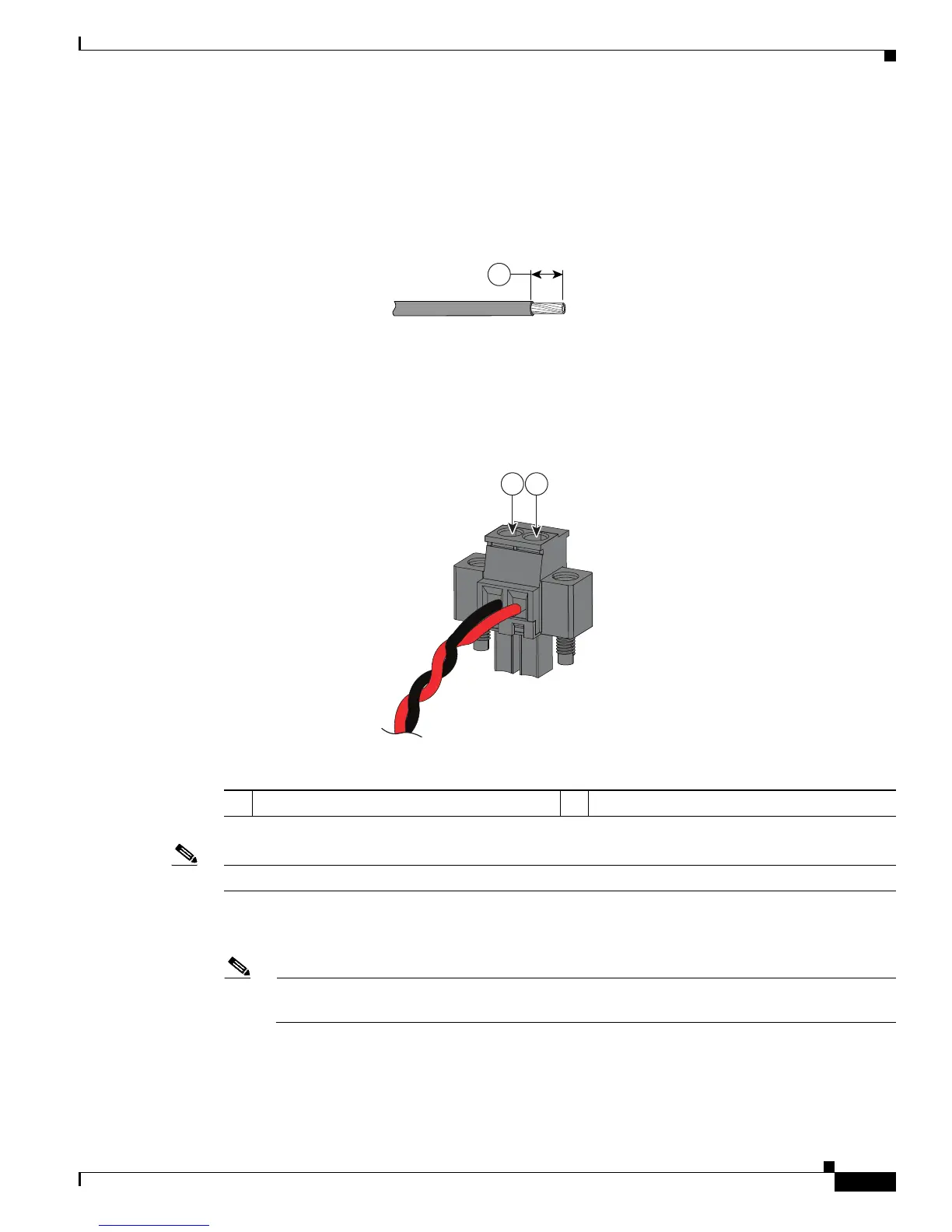
Step 4 Using a 18-gauge (1.02mm) wire-stripping tool, strip the ground wire and both ends of the twisted pair
wires to 0.25 inch (6.3 mm) ± 0.02 inch (0.5 mm). See Figure 3-4, number 1. Do not strip more than 0.27
inch (6.8 mm) of insulation from the wires. Stripping more than the recommended amount of wire can
leave exposed wire from the power and relay connector after installation.
Figure 3-4 Stripping the Power Connection Wire
Step 5
Remove the two captive screws that attach the power connector to the device, and remove the power
connector. Remove both connectors if you are connecting to two power sources
Step 6 On the power connector, insert the exposed part of the positive wire into the connection labeled “+” and
the exposed part of the return wire into the connection labeled “–”. See Figure 3-5.
Figure 3-5 Inserting Wires into the Power Connector
Note Ensure that you cannot see any wire lead. Only wire with insulation should extend from the connector.
Step 7 Use a ratcheting torque flathead screwdriver to torque the power connector captive screws (above the
installed wire leads) to 2 in-lb (0.23 N-m). See Figure 3-6.
Note Do not over-torque the power connector’s captive screws. The torque should not exceed 2
inch-lbs (0.23 N-m).
406053
2 1
1 Power source positive connection 2 Power source return connection

 Loading...