3-42
Cisco ISA 3000 Industrial Security Appliance Hardware Installation Guide
Chapter 3 Connecting the ISA 3000
Connecting Alarm Circuits
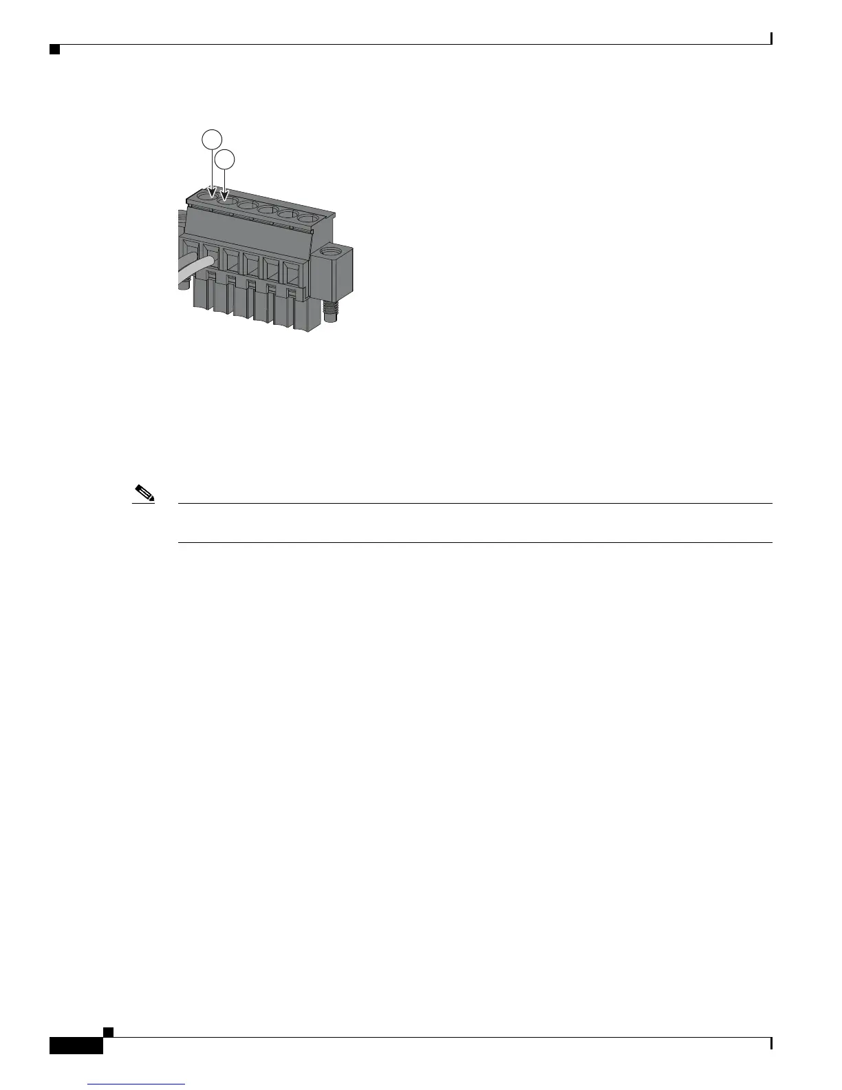
Figure 3-7 Inserting Wires into the Alarm Connector (Alarm Input Circuit)
Step 5
Use a ratcheting torque flathead screwdriver to tighten the alarm connector captive screw (above the
installed wire leads) to 2 in-lb (0.23 N-m).
Note Do not over-torque the power and alarm connectors’ captive screws. Do not exceed 2 inch-lbs (0.23 N-m)
torque.
Step 6 Repeat the above steps to insert the input and output wires of one additional external alarm device into
the alarm connector.
Figure 3-8 shows the completed wiring for two external alarm devices. The first alarm device circuit is
wired as an alarm input circuit; the IN1 and REF connections complete the circuit. The second alarm
device circuit is wired as an alarm output circuit that works on a normally open contact basis; the NO
and COM connections complete the circuit.
1 IN1 - External device connection 1
2
REF - External device connection 2

 Loading...