signal. An alarm output and the common wiring connection are required to complete a single alarm output
circuit.
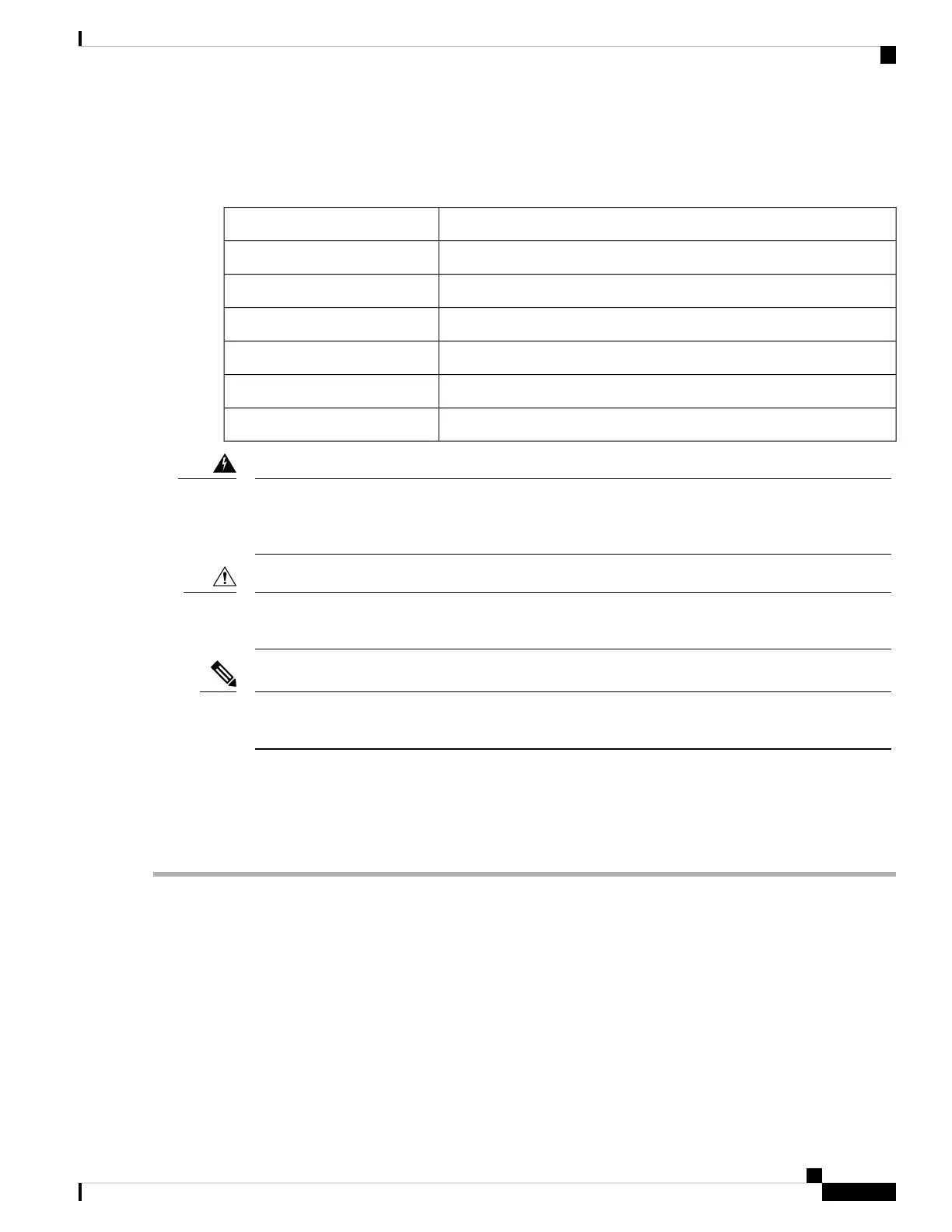
The alarm connectors are on the device panel and are detailed in the following table:
ConnectionPin
Alarm Output Normally Open (NO) connection1
Alarm Output Common connection2 (COM)
Alarm Output Normally Closed (NC) connection3
Alarm Input 24 (IN2)
Alarm Input Reference Ground connection5 (REF)
Alarm Input 16 (IN1)
Explosion Hazard—Do not connect or disconnect wiring while the field-side power is on; an electrical
arc can occur. This could cause an explosion in hazardous location installations. Be sure that power is
removed or that the area is nonhazardous before proceeding. Statement 1081
Warning
The input voltage source of the alarm output relay circuit must be an isolated source and limited to less
than or equal to 24 VDC, 1.0 A or 48 VDC, 0.5 A.
Caution
Wire connections to the power and alarm connectors must be UL- and CSA-rated, style 1007 or 1569
twisted-pair copper appliance wiring material (AWM) wire (such as Belden part number 9318).
Note
Wiring the External Alarms
To wire the device to an external alarm device, follow these steps:
Step 1 Remove the captive screws that hold the alarm connector on the device, and remove the connector from the device chassis.
Step 2 Measure two strands of twisted-pair wire (18-to-20 AWG) long enough to connect to the external alarm device.
You can choose between setting up an external alarm input or output circuit.
Step 3 Use a wire stripper to remove the casing from both ends of each wire to 0.25 inch (6.3 mm) ± 0.02 inch (0.5 mm).
Do not strip more than 0.27 inch (6.8 mm) of insulation from the wires. Stripping more than the recommended amount
of wire can leave exposed wire from the alarm connector after installation.
Step 4 Insert the exposed wires for the external alarm device into the connections based on an alarm input or output circuit setup.
For example, to wire an alarm input circuit, complete the IN1 and REF connections as shown in the following figure:
Connecting the Cisco ISA 3000
9
Connecting the Cisco ISA 3000
Wiring the External Alarms

 Loading...