EasyManuals Logo

Cisco MDS 9000 Series Installation Guide

Cisco MDS 9000 Series
20 pages
To Next Page IconTo Next Page
To Previous Page IconTo Previous Page
Page #12 background imageLoading...
Page #12 background image
If the switch has port-side exhaust modules (fan modules with blue coloring), position the switch so that its fan
and power supply modules is in the cold aisle.
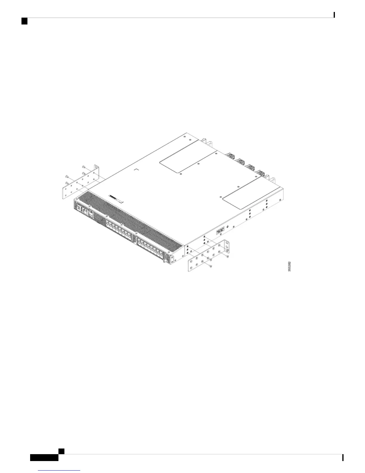
b) Position a rack–mount bracket so that four of its screw holes are aligned to the screw holes on the side of the chassis.
Then, secure the front-mount bracket to the chassis using four M4 screws.
You can align four of the holes in the front rack-mount bracket to four of the screw holes on the front side
of chassis or four of the screw holes on the rear side of the chassis. The holes that you use depend on which
side of your chassis needs to be put in the cold aisle.
Note
Figure 5: Installing Rack-mount Brackets on the Front Side of the Chassis
Installing a Cisco MDS 9132T Switch
12
Installing a Cisco MDS 9132T Switch
Installing the Switch into a 2-Post Rack

Other manuals for Cisco MDS 9000 Series

Questions and Answers:

Question and Answer IconNeed help?

Do you have a question about the Cisco MDS 9000 Series and is the answer not in the manual?

Cisco MDS 9000 Series Specifications

General IconGeneral
CategorySwitch
Operating SystemCisco NX-OS
PortsVaries by model
ProtocolsFibre Channel (FC), Fibre Channel over IP (FCIP), iSCSI
RedundancyRedundant supervisors, power supplies, and fans
ManagementCisco Data Center Network Manager (DCNM), CLI, SNMP
Virtualization SupportVSANs (Virtual SANs)
Security FeaturesFibre Channel Security Protocol (FC-SP)
Hot Swappable Componentspower supplies, fans
Power Supply OptionsAC and DC options available

Related product manuals