Installing and Removing Power Supplies
This section provides instructions for installing and removing the power supplies in the Cisco MDS 9132T
Switch.
Installing Power Supplies
You can replace one power supply while the other one provides power to the switch.
Before you begin
If the PSU blank module is inserted, remove it as follows:
1. Unscrew the locking screw.
2. Gently pull the power supply blank module out of the bay.
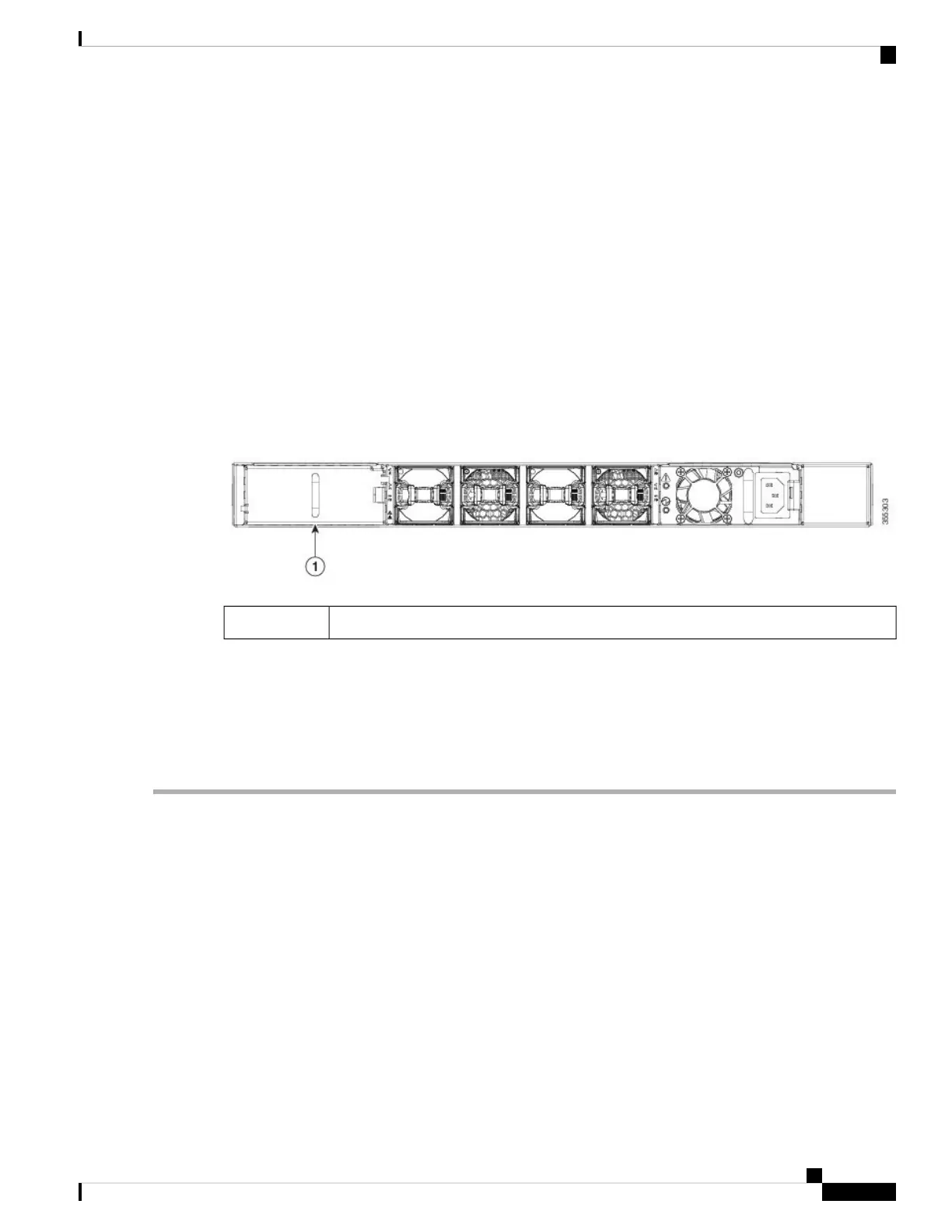
Figure 8: Inserted Power Supply Blank Module
Power supply blank module1
• To implement n+n redundancy, there must be two external power sources and two PSUs attached to each
power source. Otherwise, only one power source is required.
• There must be an earth ground connection to the chassis to which you are installing the replacement
module. Typically, the chassis is grounded by its metal-to-metal connection with a grounded rack. If you
need to ground the chassis, see Grounding the Switch.
Step 1 Holding the power supply unit with one hand underneath it and the other hand holding the handle, turn the power supply
so that its release latch is on the right side, and align the back end of the power supply (the end with the electrical
connections) to the open power supply slot. Carefully slide the power supply unit all the way into the slot until it clicks
into place.
If the power supply unit does not fit into the slot opening, turn the unit over and try again.
Note
Step 2 Test the installation by trying to pull the power supply out of the slot without using the release latch.
If the power supply does not move out of place, it is secured in the slot. If the power supply moves, carefully press it all
the way into the slot until it clicks in place and tighten the locking screw.
Step 3 Attach the power cable to the electrical outlet on the front of the power supply.
Step 4 Make sure that the other end of the power cable is attached to the appropriate power source for the power supply. If the
power source has a switch, slide it to the On position.
Installing a Cisco MDS 9132T Switch
17
Installing a Cisco MDS 9132T Switch
Installing and Removing Power Supplies

 Loading...