Send documentation comments to n5kdocfeedback@cisco.com
1-18
Cisco Nexus 5000 Series NX-OS Interfaces Operations Guide, Release 5.0(3)N2(1)
Chapter 1 Virtual Port Channel Operations
Tracing Traffic Flow in a vPC Topology
split-brain scenario. Because the peer link is no longer available, the two vPC switches cannot
synchronize the unicast MAC address and the IGMP group and therefore they cannot maintain the
complete unicast and multicast forwarding table. This situation is rare.
We recommend that you have a well-planned network design that includes spreading peer links and
keepalive links to multiple ASICs or multiple modules and different cabling routes for keepalive and
peer links to avoid a double failure.
Tracing Traffic Flow in a vPC Topology
This section describes how to trace a traffic flow in a vPC topology that is similar to a port-channel
environment.
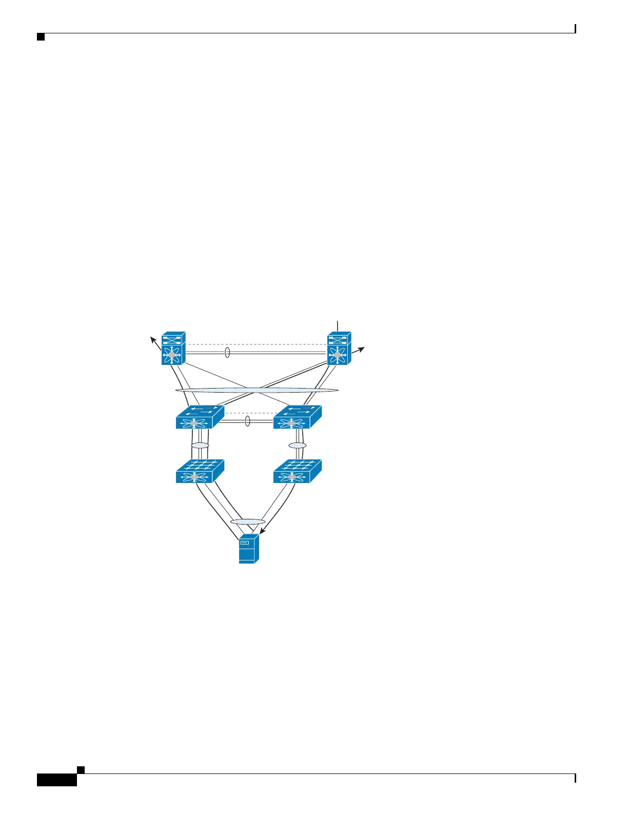
Figure 1-3 shows that each hop in the network chooses one vPC member port to carry the traffic flow
independently.
Figure 1-3 Traffic Flow in a vPC Topology
In this example, for flow 1, the host makes a decision whether the traffic flow is sent to the FEX on left
or the right side. The FEX runs its hash algorithm to choose one uplink to carry the flow. The N5k
determines if the flow should be sent to N7k1 or N7k2. When the egress port for a traffic flow is a vPC,
the vPC switch always prefers to use its own vPC member port to carry the traffic in order to minimize
the utilization of peer links.
The Cisco NX-OS and Cisco IOS software includes commands to identify the port channel member that
carries a particular flow.
This example assumes that the default hash algorithm is used which is src-mac, dst-mac, src-ip and
dst-ip. If the hash algorithm also includes the Layer 4 UDP/TCP port, the port information also needs to
be provided in the command. The port channel in the command should be the egress port channel.
Po10
Po20
281856
5k025k01
7k01 7k02
Flow 1
Flow 2
Flow 3

 Loading...