Send documentation comments to n5kdocfeedback@cisco.com
2-2
Cisco Nexus 5000 Series NX-OS Interfaces Operations Guide, Release 5.0(3)N2(1)
Chapter 2 Cisco Nexus 5500 Platform Layer 3 and vPC Operations
ARP Processing with vPC
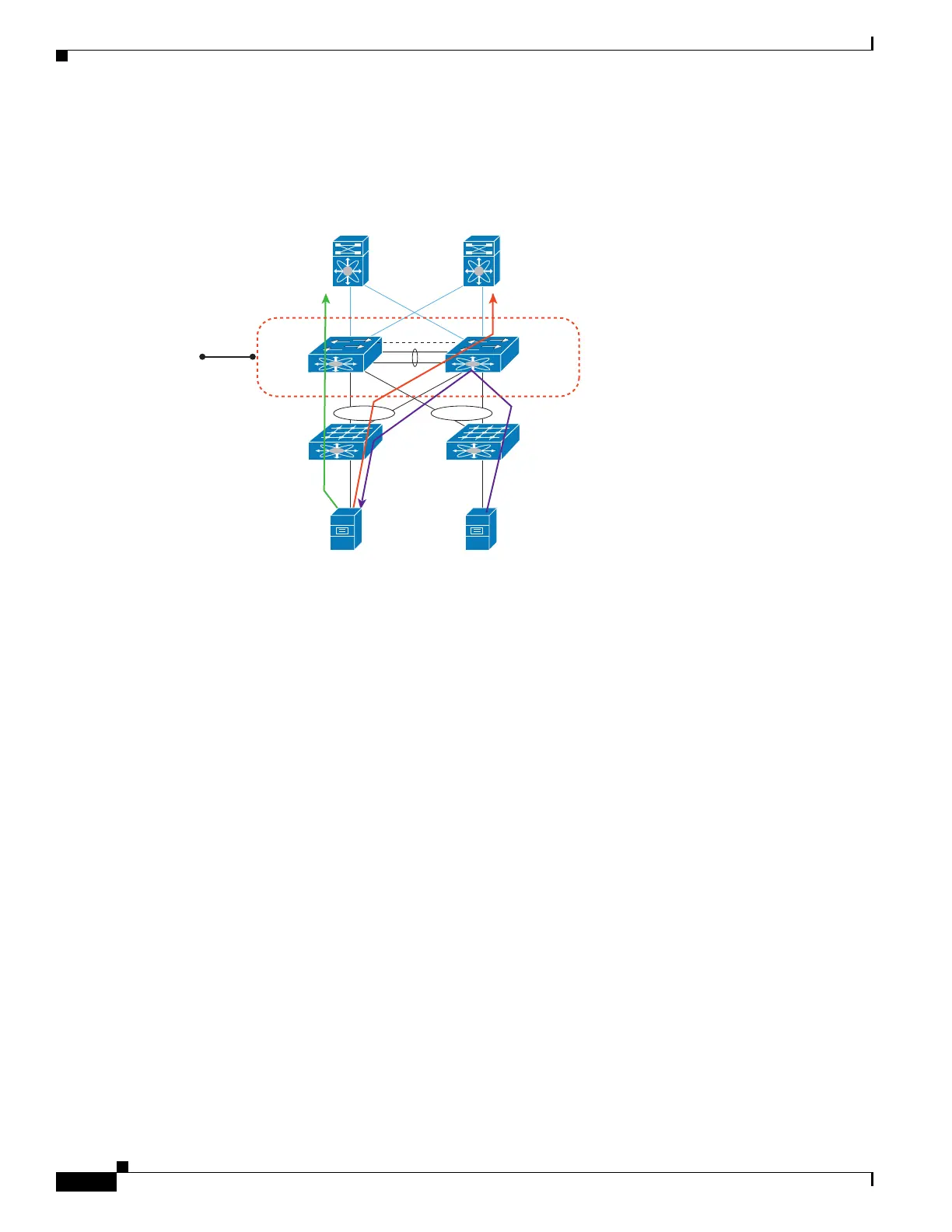
Figure 2-1 shows that the Layer 3 traffic that originated from the host and is destined to a host several
hops away can be routed by both the Host Standby Router Protocol (HSRP) active and the HSRP standby
switch..
Figure 2-1 vPC and FHRP
ARP Processing with vPC
When the host connects to a Cisco Nexus 5500 Platform switch and Cisco Nexus 2000 Fabric Extenders
in a vPC topology, the host can send an ARP request to the FHRP standby peer due to a hashing
algorithm. The ARP request that is received by the standby peer is forwarded to the active peer and the
active peer can answer it with an ARP reply.
Similarly, when traffic is moving from north to south, such as when one Cisco Nexus 5500 Platform
switch sends an ARP request to a host, the ARP reply might be sent to another switch. In such a case,
the ARP reply is forwarded as a Layer 2 frame to the Cisco Nexus 5500 Platform switch that originated
the ARP request.
As of Cisco NX-OS Release 5.0(3)N1(1b), ARP synchronization does not occur between two Cisco
Nexus 5500 Platform switches. The two switches resolve and maintain their ARP table independently.
When one vPC peer switch is reloaded, the switch needs to resolve the ARP by sending ARP requests
to the hosts.
Layer 3 Forwarding for Packets to a Peer Switch MAC
Address
Typically, a router performs a Layer 3 route table lookup and Layer 3 forwarding when the destination
MAC in the Ethernet frame matches its own MAC address. Otherwise, the packets are switched (if Layer
2 functionality is enabled) or dropped. In a topology with Layer 3 and vPC enabled, a vPC peer switch
could receive IP packets with the peer’s MAC address as the destination MAC rather than the virtual
vPC1 vPC2
VLAN 10 VLAN 20
HSRP
Standby
HSRP
Active
L3
L2
239429

 Loading...