1-28
Cisco ONS 15454 Procedure Guide, Release 8.5.1
78-18537-01
Chapter 1 Install the Shelf and Backplane Cable
NTP- A11 Install the Rear Cover
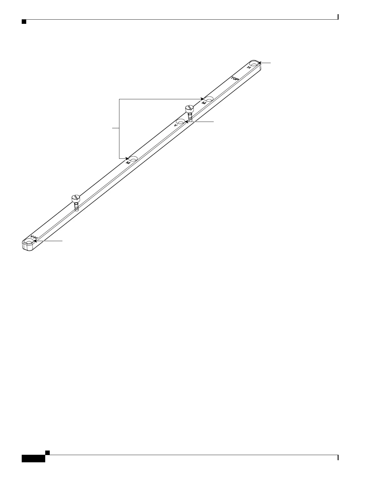
Figure 1-11 EIA Labeling on the Mounting Bar
Step 6
Tighten the two screws (48-2116-01) for each mounting bar.
Step 7 Repeat Steps 5 and 6 for the second mounting bar.
Step 8 Attach the rear cover (700-06029-XX) by hanging it from the mounting screws on the back of the
mounting bars and pulling it down until it fits firmly into place (Figure 1-12) or by using standoffs
(Figure 1-13).
115479
Mounting holes
for all other EIAs
UBIC-H
mounting hole
UBIC-V
mounting hole
UBIC-V/UBIC-H
mounting hole

 Loading...


