11
3 System Installation
This chapter describes the system installation of the Cisco Service Control solution.
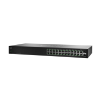
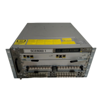
Installing the Cisco SCE 8000 Platform
To install the Cisco SCE 8000 platform, complete the following steps. (For more information, see the Cisco SCE 8000 10GBE
Installation and Configuration Guide or the Cisco SCE 8000 GBE Installation and Configuration Guide.)
Step 1 Install the Cisco SCE platform on the rack.
Step 2 Connect the chassis ground and the power.
Step 3 Connect the CON port to a local terminal. Configure the initial setup parameters as necessary. (See the “Initial
Configuration of the Cisco SCE 8000 Platform” section on page 31).
Step 4 Connect the MNG port to the local LAN.
Step 5 Cable the line ports. (See the“Cisco SCE 8000 Connectivity” section on page 11 for a summary of proper cabling for
various topologies).
Cisco SCE 8000 Connectivity
Table 1, Table 2, Table 3, Table 4, and Table 5 summarize Cisco SCE 8000 connectivity for the basic topologies.
Note Receive-only topologies use only Receive fibers. these can be implemented by using either an optical splitter or a switch.
If a switch is used, it must support SPAN functionality that includes separation between ingress and egress traffic and
multiple SPAN ports destinations.
Table 1 Single-Link Inline Connectivity
Port Link Side
3/0/0 Link 0 Subscribers
3/1/0 Link 0 Network
Table 2 Dual-Link Inline Connectivity
Port Link Side
3/0/0 Link 0 Subscribers
3/1/0 Link 0 Network
3/2/0 Link 1 Subscribers
3/3/0 Link 1 Network
Table 3 Cascade Connectivity
This port on Cisco SCE 8000 #1 Connects to...
3/0/0 Subscriber-side network element
3/1/0 Network-side network element
3/2/0 (cascade port) Port 3/3/0 on Cisco SCE 8000 #2
 Loading...