3-18
Cisco UCS C200 Server Installation and Service Guide
OL-20732-02
Chapter 3 Maintaining the Server
Installing or Replacing Components
–
If you have the LFF version of the server with 3.5-in drives, the four screws install on the bottom
of the sled.
–
If you have the SFF version of the server with 2.5-in drives, two screws install on each side of
the sled.
c. With the ejector lever still open, push the sled into the drive bay until you feel the drive stop against
the backplane.
d. Press the ejector lever flat until the lock clicks into place.
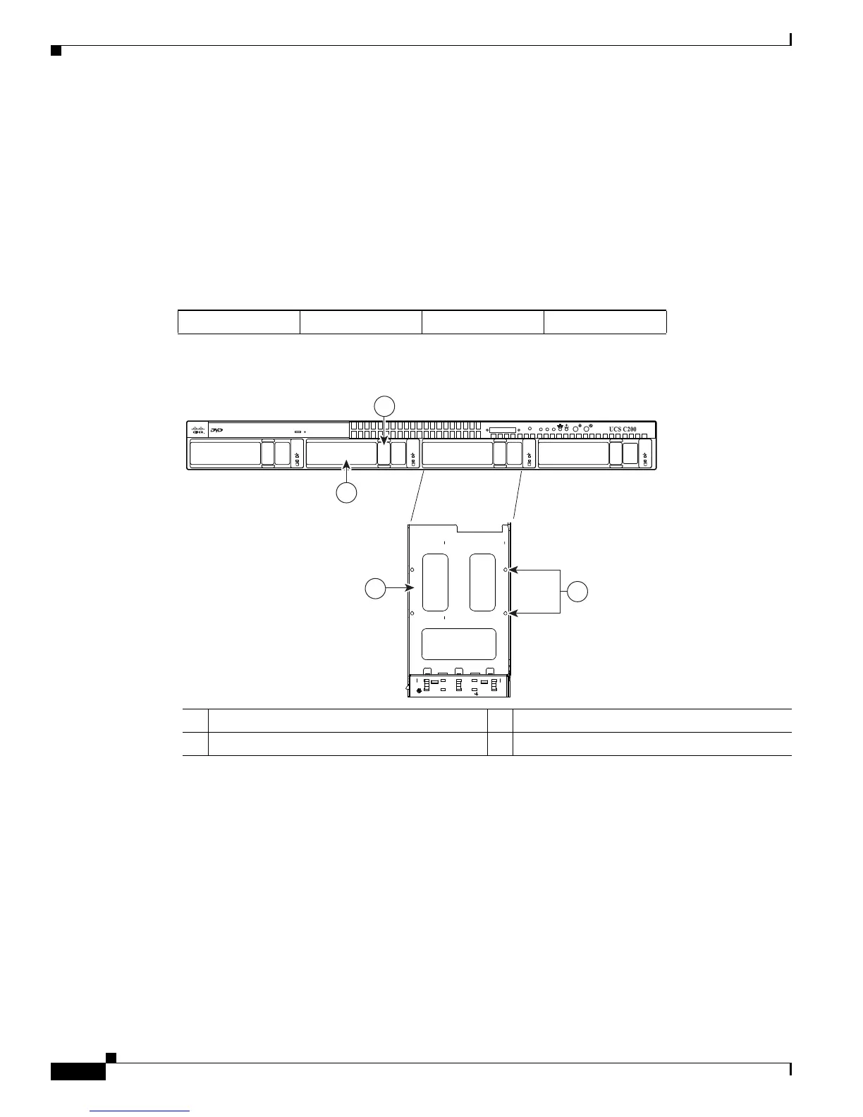
Figure 3-10 Drive Numbering and Physical Orientation, Facing Server Front (Large Form Factor)
Figure 3-11 Removing and Replacing Hard Drives (Large Form Factor)
HDD_01 HDD_02 HDD_03 HDD_04
1 Release button 3 Hard drive sled, bottom view
2 Ejector lever 4 Securing screws (four)
3
4
195725
Console
Reset
PSU
MEM
CPU
2
1