3-42
Cisco UCS C200 Server Installation and Service Guide
OL-20732-02
Chapter 3 Maintaining the Server
Installing or Replacing Components
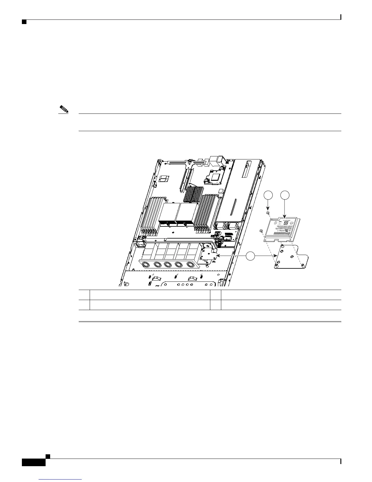
b. Place the new BBU over the BBU bracket on the fan tray and align the three screw-holes in the BBU
with the three preinstalled standoffs on the bracket.
c. Replace the three securing screws that hold the BBU to the BBU bracket.
Step 3 If this is a first-time installation of the BBU rather than a replacement, install the cable from the BBU
to the LSI card.
Connect the cable from the BBU to the socket on the adapter.
Note Be careful to align the arrow-mark on the cable connector with the arrow-mark on the socket to avoid
damaging the connector pins.
Figure 3-24 Removing and Replacing an LSIiBBU06 BBU
1 BBU bracket on fan tray 3 BBU (connector J2 is on the underside)
2 Securing screws (three)