3-13
Cisco UCS C22 Server Installation and Service Guide
OL-26646-01
Chapter 3 Maintaining the Server
Installing or Replacing Server Components
g. Slide the board back from the front panel openings until the keyed slots on the front corners of the
board can be lifted over the chassis pegs.
h. Lift the board up and off the pegs and remove it from the chassis.
Step 2 Replace a front operations panel board:
a. Set the board in place with the keyed slots in the front corners of the board over the two chassis pegs.
Note When you slide the board forward in the next step, be careful to align the LED light-pipes on the
board with the openings in the server front panel.
b. Slide the board forward to lock the keyed slots onto the pegs.
c. Replace the two screws that secure the board to the chassis.
d. Reconnect the two ribbon cables to the board.
Open a hinged connector and insert the end of a ribbon cable squarely into the connector until it
stops, and then close the hinged connector.
Note The side of the cable end that is colored blue should face upward.
e. Replace the front chassis panel.
f. Replace the top cover.
g. Replace the server in the rack, replace cables, and then power on the server by pressing the Power
button.
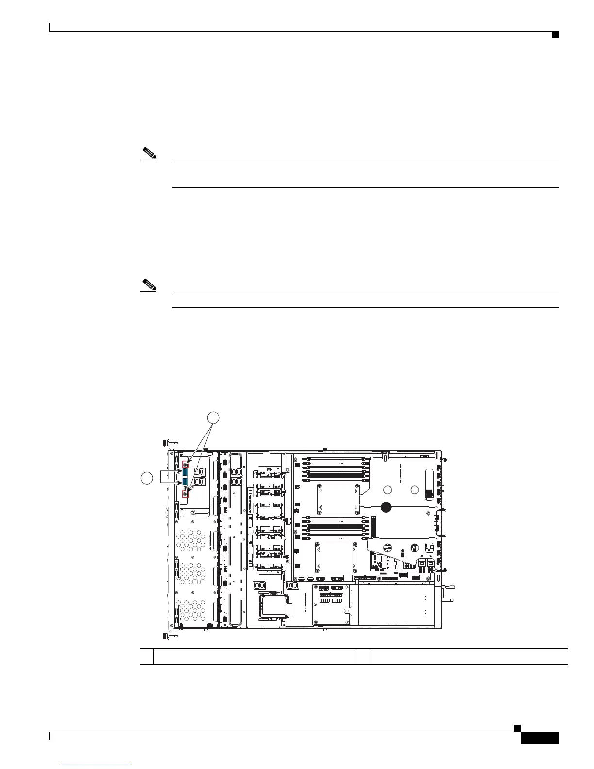
Figure 3-7 Replacing the Front Operations Panel Board
1 Hinged ribbon-cable connectors (two) 2 Securing screws (two)
PCIe 1
PCIe 2
PSU 1
SYS FAN1
SYS FAN2
SYS FAN3
SYS FAN4
CPU 1
CPU 2
SYS FAN5
285206
2
1