3-11
Cisco UCS C220 M4 Server Installation and Service Guide
OL-32473-01
Chapter 3 Maintaining the Server
Installing or Replacing Server Components
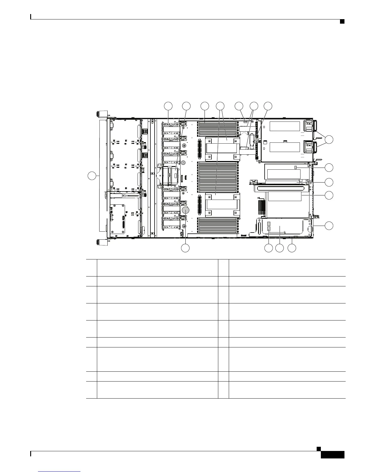
Replaceable Component Locations
This section shows the locations of the field-replaceable components. The view in Figure 3-5 is from the
top down with the top cover and air baffle removed.
Figure 3-5 Replaceable Component Locations
The Technical Specifications Sheets for all versions of this server, which include supported component
part numbers, are at Cisco UCS Servers Technical Specifications Sheets.
1 Drives (SAS/SATA drives are hot-swappable) 10 Trusted platform module (TPM) socket on
motherboard (not visible in this view)
2 Cooling fan modules (six) 11 PCIe riser 2 (half-height PCIe slot 2)
3 Supercap Power Module (RAID backup)
mounting bracket
12 PCIe riser 1 (full-height PCIe slot 1)
4 DIMM sockets on motherboard (24) 13 Modular LOM (mLOM) connector on chassis
floor
5 CPUs and heatsinks (up to two) 14 Cisco modular RAID controller PCIe riser
(dedicated riser with horizontal socket)
6 Embedded SATA RAID header for RAID 5 key 15 Cisco modular RAID controller card
7 SD card bays on motherboard (two) 16 Embedded SATA RAID mini-SAS
connectors on motherboard (not visible in
this view)
8 Internal USB 3.0 port on motherboard 17 RTC battery on motherboard
9 Power supplies (up to two, hot-swappable
when redundant as 1+1)
352978
FAN 6
FAN 5
FAN 4
FAN 3
FAN 2
FAN 1
CPU 2
CPU 1
PSU 2
PSU 1
PCIe Riser 1
PCIe Riser 2
SD 1
SD 2
1
2
4 5
67
8
9
10
11
12
13
1617 15 14
3
 Loading...


