13
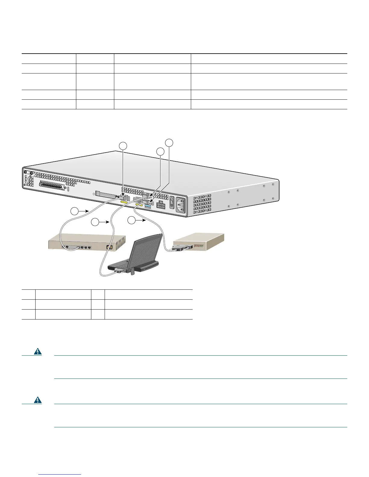
Figure 12 LAN, Administrative Access, and Power Connections
Connecting WAN and Voice Cables
Warning
For connections outside the building where the equipment is installed, the following ports must be connected
through an approved network termination unit with integral circuit protection.
FXS/T3/E3
Statement 1044
Also, the following warning applies to the RJ-21 interface.
Warning
This equipment contains a ring signal generator (ringer), which is a source of hazardous voltage. Do not touch the
RJ-11 (phone) port wires (conductors), the conductors of a cable connected to the RJ-11 port, or the associated
circuit-board when the ringer is active. The ringer is activated by an incoming call.
Statement 1042
These cables and connections are described in Table 3 and Figure 13.
Table 2 LAN, Administrative Access, and Power Cable Selection
Port or Connection Color or Type Connected To Cable
Fast Ethernet Yellow Fast Ethernet hub Straight-through Fast Ethernet cable (not included)
Console Light blue PC or ASCII terminal
communication (COM) port
RJ-45-to-DB9 console cable (included)
Auxiliary Black Modem for remote access RJ-45-to-DB25 auxiliary cable (included)
Power Power 100–240 VAC, 50–60 Hz Grounding power cord (included)
1
1. Power cables vary to meet local requirements.
1
Fast Ethernet port
4
Fast Ethernet (straight-through)
2
Console port
5
RJ-45-to-DB9 console cable
3
AUX port
6
RJ-45-to-DB25 auxiliary cable
95920
VG224-24FXS
4
5
6
Ethernet hub
1
2
3
Cisco VG224
Modem
PC

 Loading...


