Statement 1047—Overheating Prevention
To reduce the risk of fire or bodily injury, do not operate the unit in an area that exceeds the maximum
recommended ambient temperature of: 40 degrees C.
Warning
What to do next
After you install the voice gateway, you must connect the chassis to a reliable earth ground. For the chassis
ground connection procedures, see the Chassis Grounding section in this hardware installation guide.
Chassis Grounding
To install the ground connection for your router, perform the following steps:
Before you begin
Use a size 10 AWG (4 mm2) or larger copper wire and an appropriate user-supplied ring terminal with an
inner diameter of 1/4 in. (5–7 mm).
Step 1 Strip one end of the ground wire to the length required for the ring terminal.
Step 2 Crimp the ground wire to the ring terminal, using a crimp tool of the appropriate size.
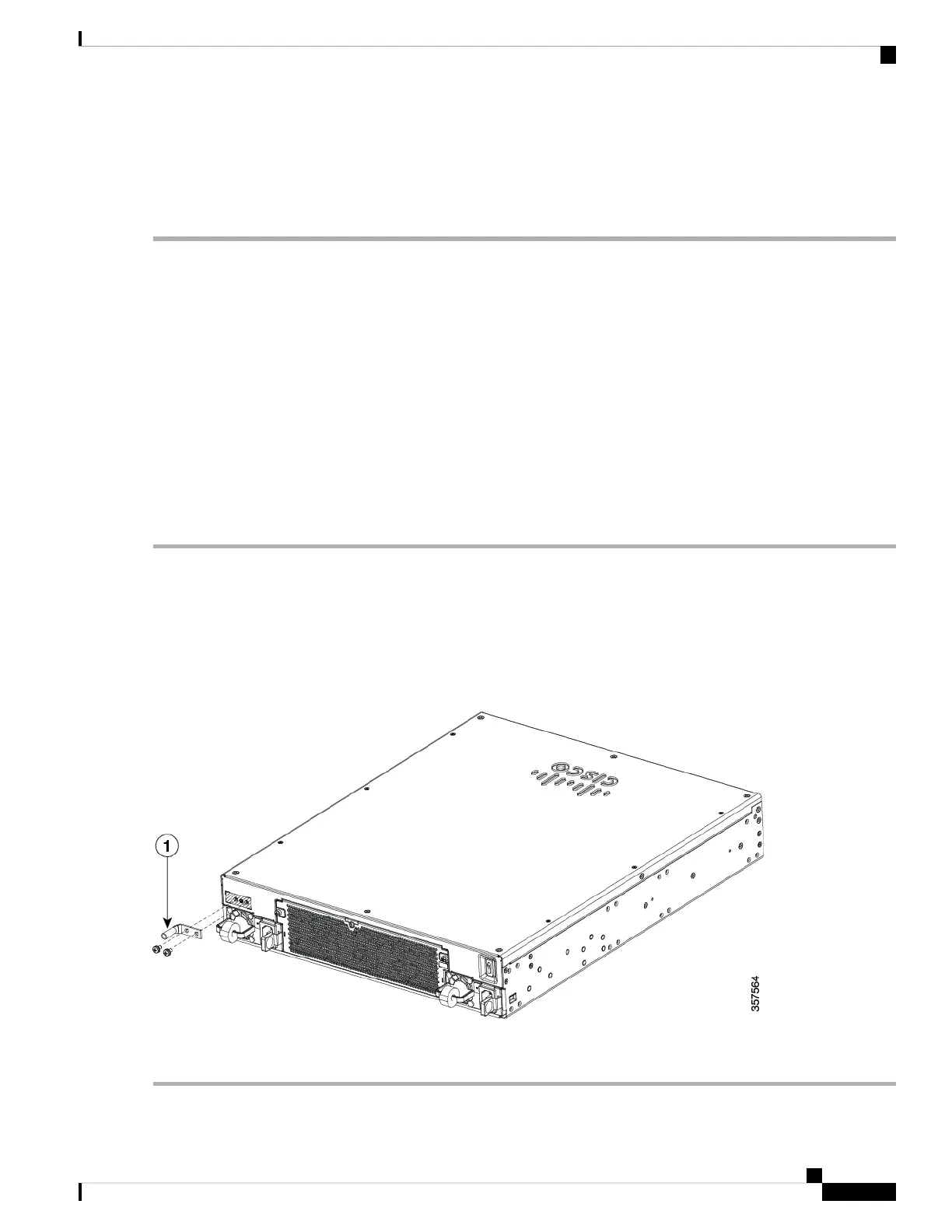
Step 3 Attach the ground lug or ring terminal to the chassis as shown in the following image. Use one of the screws provided.
Tighten the screws to a torque of 8 to 10 in-lb (0.9 to 1.1 N-m).
Step 4 Connect the other end of the ground wire to a known reliable earth ground point at your site.
Figure 6: Chassis Grounding
In the above image, 1 indicates Ground Lug.
Installing the Cisco VG420 Voice Gateway
9
Installing the Cisco VG420 Voice Gateway
Chassis Grounding