3-21
Cisco 2900 and 3900 Series Hardware Installation
OL-18712-01
Chapter 3 Installing and Connecting the Router
Connecting Power
Warning
When stranded wiring is required, use approved wiring terminations, such as closed-loop or
spade-type with upturned lugs. These terminations should be the appropriate size for the wires and
should clamp both the insulation and conductor.
Statement 1002
Step 2
Strip the wires to the appropriate length for the terminals. The strip length is 5/64 to 1/8 inch (2 to 4
mm) for Amp/Tyco No. 32957 terminals.
Step 3
Crimp the terminals to the power input and safety ground wires.
Step 4
Remove the plastic covers from the terminal block. Save the covers for reinstallation after you finish
wiring.
Step 5
Connect the wires to the terminal block, starting with the safety ground wire. Connect each wire to the
appropriate terminal as shown in Figure 1. Tighten the terminal screws to 8.0 ± 0.5 in-lb (0.9 ± 0.05
N-m).
Warning
This unit might have more than one power supply connection. All connections must be removed to
de-energize the unit.
Statement 1028
Warning
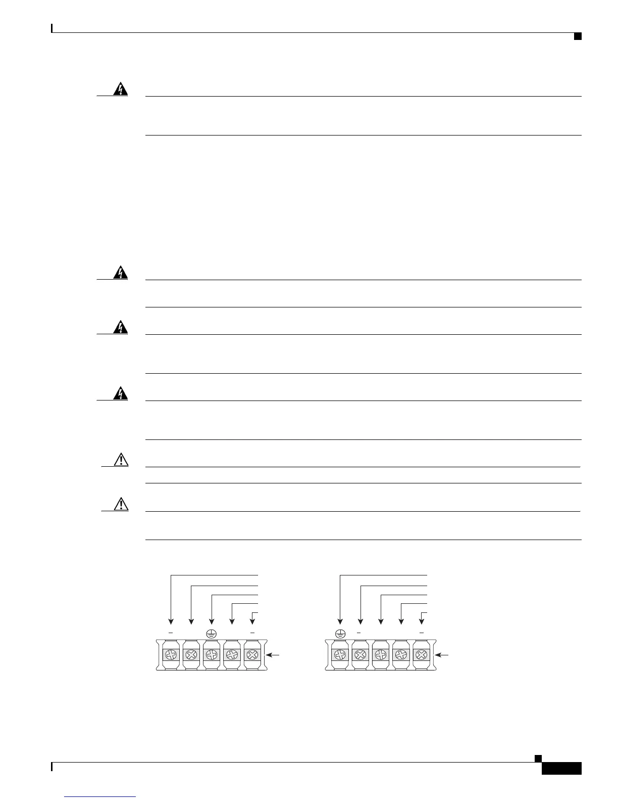
The illustration shows the DC power supply terminal block. Wire the DC power supply as illustrated.
The proper wiring sequence is ground to ground, positive to positive, and negative to negative. The
ground wire should always be connected first and disconnected last.
Statement 239
Warning
An exposed wire lead from a DC-input power source can conduct harmful levels of electricity. Be sure
that no exposed portion of the DC-input power source wire extends from the terminal block plug.
Statement 122
Caution
Dual sources with opposite-polarity grounding damage equipment.
Caution
Caution Do not overtorque the terminal block contact screws. Recommended torque is 5.0 ± 0.5 in-lb
(0.56 ± 0.06 N-m) for 2911 series routers, and 9 ± 1.0 in-lb (1.02 ± 0.11 N-m)
Figure 3-20 DC Power Connections for Cisco 2911, 2921, and 2951 Routers
A ++B
2921/2951
Terminal
block
A ++B
2911
Terminal
block
279991
-DC, input A
Return, input A
Safety ground
Return, input B
- DC, input B
Safety Ground
-DC, input A
Return, input A
Return, input B
-DC, input B
 Loading...