Do you have a question about the Cisco WS-C2950-12 and is the answer not in the manual?
Identifies the intended reader for this installation guide.
Describes the scope and content of the hardware installation guide.
Details the chapter and appendix structure of the manual.
Explains symbols and text conventions used in the publication.
Instructions for accessing Cisco documentation via the World Wide Web.
Information on obtaining Cisco documentation via CD-ROM.
Details on how to order printed Cisco product documentation.
Instructions for providing feedback on Cisco product documentation.
Information on accessing Cisco's online services and support resources.
Details Cisco's Technical Assistance Center (TAC) services and support levels.
Information on accessing Cisco's TAC website for support resources.
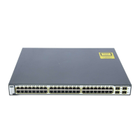
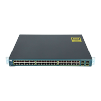
Describes the hardware features of the Catalyst 2950 switches.
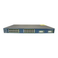
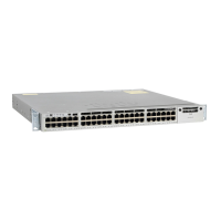
Details the components and indicators on the front panel of the switch.
Explains the specifications and connectivity of the 10/100 Ethernet ports.
Describes the specifications and connectivity of the 10/100/1000 Ethernet ports.
Details the fiber-optic ports and their specifications.
Describes the Gigabit Interface Converter (GBIC) module slots.
Explains the function and meaning of the switch's LEDs.
Describes the status and meaning of the System LED.
Explains the status indicators for the Redundant Power System (RPS).
Details how port LEDs indicate status and how to change port modes.
Details the components and connectors on the rear panel of the switch.
Information on connecting power to the switch using various methods.
Details the internal AC power supply connector.
Describes the DC power connector for specific switch models.
Explains the connection and function of the Cisco RPS.
Details how to connect a PC or terminal to the switch's console port.
Outlines the different methods for managing the switch.
Covers essential steps and considerations before installing the switch.
Lists critical safety warnings that must be observed during installation.
Provides specific electromagnetic compatibility (EMC) regulatory information.
US regulatory information for EMC compliance.
Taiwanese regulatory information for EMC compliance.
Japanese regulatory information for EMC compliance.
Korean regulatory information for EMC compliance.
Hungarian regulatory information for EMC compliance.
Provides recommendations for optimal switch placement and installation.
Instructions for checking that all items are included in the product package.
Step-by-step guide for securely mounting the switch in a rack.
Detailed instructions on how to attach mounting brackets to the switch.
Procedure for securely fixing the switch into the rack using machine screws.
Instructions for attaching the cable guide for better cable management.
Guide for placing the switch on a surface like a table or desk.
Instructions for inserting Gigabit Interface Converters (GBICs) into module slots.
Steps to power on the switch after installation and connection.
Detailed steps for connecting the switch to a DC power source.
Tools and components needed for DC power connection.
Instructions for properly grounding the switch for safety and performance.
Guidance on correctly wiring the DC power source to the switch.
How to connect devices to the switch's 10/100 and 10/100/1000 ports.
Instructions for connecting devices to fiber-optic ports.
Overview of connecting devices to GBIC module ports.
Steps for connecting devices to 1000BASE-X GBIC module ports.
Steps for connecting devices to 1000BASE-T GBIC module ports.
Instructions for connecting devices using GigaStack GBIC ports.
Guide for establishing a console connection for initial setup.
Directs users to further documentation for configuration and startup.
Explains how to interpret the results of the Power-On Self-Test (POST).
Provides a systematic approach to identifying and solving switch issues.
Details the specifications for different types of connectors on the switch.
Describes the RJ-45 connector and pinout for 10/100 Ethernet ports.
Details the RJ-45 connector and pinout for 10/100/1000 Ethernet ports.
Describes the MT-RJ connector for fiber-optic ports.
Describes the proprietary connector for GigaStack GBIC module ports.
Details the RJ-45 connector for the console port.
Provides pinout details for various cables and adapters used with the switch.
Instructions for correctly attaching the Cisco RPS to the switch.
Warning regarding electrical safety during lightning storms.
Cautionary advice to read installation instructions before connecting power.
Emphasizes the importance of accessible power connection points.
Safety guidelines for mounting and servicing the unit in a rack.
Warning about operating the switch within specified temperature limits.
Warning about unplugging the power cord on systems without an on/off switch.
Ensures proper grounding of the equipment for safety.
Guidance on the proper disposal of the product according to regulations.
Highlights the correct procedure for making and breaking ground connections.
Warning to remove jewelry before working with powered equipment.
Caution against stacking units to prevent injury or damage.
Specifies that only trained and qualified personnel should install or service the equipment.
Warning regarding the Class 1 laser product classification.
Warning to avoid exposure to laser beams.
Specifies that this model has no field-replaceable units (FRUs).
Warning that the equipment must be installed in a restricted access area.
Requirement for shielding Ethernet cables in central office environments.
Safety procedures for disconnecting DC power circuits.
Warning about the danger of exposed DC power wires.
Specifies that only qualified service personnel should handle the equipment.



 Loading...