Chapter 2 Installation
Running POST
2-32
Catalyst 2950 Desktop Switch Hardware Installation Guide
78-11157-03
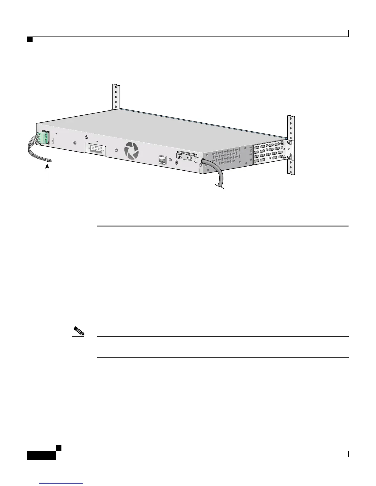
Figure 2-30 Inserting the Terminal Block in the Block Header
Step 8
Remove the tape from the circuit-breaker switch handle, and move the
circuit-breaker handle to the on position.
Running POST
After the power is connected, the switch automatically begins POST, a series of
tests that verifies that the switch functions properly. When the switch begins
POST, the system LED is off. If POST completes successfully, the LED turns
green. If POST fails, the LED turns amber. See Chapter 3, “Troubleshooting,” to
determine a corrective action.
Note POST failures are usually fatal. Call Cisco Systems immediately if your switch
does not pass POST.
DC
INPU
T FOR
R
EM
OTE
PO
W
ER SUPPL
Y
SPEC
IFIED IN
M
AN
UAL.
+12V @
4.5A
3
6
-
7
2
V
1
-
0
.5
A
CO
NSO
LE
A
B
Tie wrap
65293