1-3
Catalyst 2950 Desktop Switch Hardware Installation Guide
78-11157-03
Chapter 1 Overview
Front-Panel Description
• Power redundancy
–
Connection for an optional Cisco RPS 300 Redundant Power System
(RPS) that uses alternating current (AC) input and supplies DC output to
the switch
Front-Panel Description
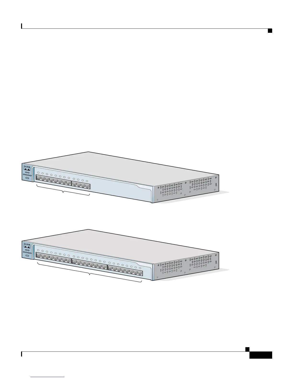
The switch front panel contains the ports, the LEDs, and the Mode button.
Figure 1-1 to Figure 1-9 show the switches.
Figure 1-1 Catalyst 2950-12 Switch
Figure 1-2 Catalyst 2950-24 Switch
10/100 ports
45568
SY
ST
RP
S
DU
P
LX
M
OD
E
S
PEE
D
UT
IL
S
TA
T
10Base-T / 100Base-TX
Catalyst 2950
SE
RIES
1x
2x
3x
4x
5x
6x
7x
8x
9x
10x
11x
12x
10/100 ports
45567
SY
S
T
RP
S
D
U
P
LX
M
O
DE
S
PE
E
D
U
TIL
S
T
AT
10Base-T / 100Base-TX
Catalyst 2950
S
E
R
IES
1
2
3
4x
5x
6x
7x
8x
9x
10x
11x
12x
13x
14x
15x
16x
17x
18x
19
x
20x
21x
22x
23x
24x