Chapter 1 Overview
Front-Panel Description
1-12
Catalyst 2950 Desktop Switch Hardware Installation Guide
78-11157-03
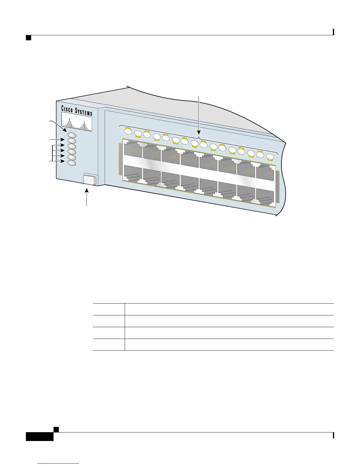
Figure 1-12 LEDs on Catalyst 2950G-48-EI Switches
System LED
The system LED shows whether the system is receiving power and functioning
properly. Table 1-2 lists the LED colors and meanings.
For information about the system LED colors during the power-on self-test
(POST), see the “Running POST” section on page 2-32.
1X
2X
15X
16X
1
2
3
4
5
6
7
8
9
10
11
12
13
14
15
16
SYST
RPS
STAT
UTIL
DUPLX
SPEED
MODE
Mode button
Port
mode
LEDs
System
LED
RPS
LED
Port status
LEDs
65508
Table 1-2 System LED
Color System Status
Off System is not powered up.
Green System is operating normally.
Amber System is receiving power but is not functioning properly.