CT-S651 Series Service Manual
- 13 -
.
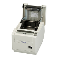
11. Disassembling “UNIT, MAIN PCB”
Remove four “SCREW, BHT (ST), M3.0 × 6”
that fasten “UNIT, MAIN PCB” and “SA, MAIN
FRAME”.
Remove one “SCREW, BHT (ST), M3.0 × 6” that
fastens “COVER, CABLE PROTECT-02” at the right
side, and disconnect the connector of “COVER OPEN
SENSOR”.
Disconnect the connectors of “SA, HEAD
CABLE-02” and “SA, PNE SENSOR” at the
left side.
Disconnect the connector of “SA, POWER SW” at the
rear.
Disconnect the connectors of “SA, PE SENSOR” and “UNIT, MOTOR” at the front, and remove “UNIT, MAIN
PCB”.
<Precaution at reassembly>
Connectors are provided at the right, left, and front sides. Be careful not to pull these cables by force.
When reassembling, be careful not to miss or catch any part, such as “FRAME”. Before disassembling
record the cable routing. When reassembling, reconnect the cables correctly. Pass “CABLE” of “COVER
OPEN SENSOR” through the hole on “COVER, CABLE PROTECT-02” and secure it.
SCREW, BHT (ST), M3.0 × 6
SCREW, BHT (ST), M3.0 × 6
COVER, CABLE PROTECT-02
J10: COVER OPEN SENSOR
Pass “COVER OPEN
SENSOR” through this hole.
J2: SA, HEAD CABLE-02
J5: SA, PNE SENSOR
J12: SA, POWER SW
J11: SA, PE SENSOR
J4: UNIT, MOTOR
 Loading...