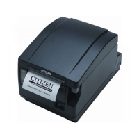
CT-S651 Series Service Manual
- 2 -
CONTENTS
INTRODUCTION .............................................................................................4
1. DISASSEMBLY AND REASSEMBLY.......................................................4
1-1. Tools Used .........................................................................................................................4
1-2. Disassembly Procedure .....................................................................................................5
1-2-1. Disassembling the Printer....................................................................................5
1-2-2. Disassembling “UNIT, MECHANISM” ................................................................14
1-3. Assembly Procedure........................................................................................................23
1-4. Oiling................................................................................................................................24
2. TROUBLESHOOTING ...........................................................................27
2-1. Error Indication.................................................................................................................27
2-2. Explanations of Error Conditions......................................................................................29
2-2-1. Paper Near End.................................................................................................29
2-2-2. Paper End..........................................................................................................29
2-2-3. Front Cover Open..............................................................................................29
2-2-4. Paper Cover Open.............................................................................................29
2-2-5. Cutter Error........................................................................................................29
2-2-6. Print Head Hot ...................................................................................................29
2-2-7. Memory Error.....................................................................................................29
2-2-8. System Error......................................................................................................29
2-2-9. Low Voltage Error ..............................................................................................30
2-2-10. High Voltage Error .............................................................................................30
2-2-11. Drawer Voltage Error .........................................................................................30
2-2-12. Macro Execution Wait........................................................................................30
2-3. Troubleshooting Procedure..............................................................................................31
2-4. Troubleshooting Guide.....................................................................................................31
3. SERVICE PARTS LIST ..........................................................................35
3-1. Mechanical Parts List.......................................................................................................35
3-1-1. Mechanical Exploded Diagrams ........................................................................41
3-2. Parts Layout.....................................................................................................................48
3-2-1. SA, MAIN PCB ..................................................................................................48
3-2-2. SA, OPEPANE PCB-651 ...................................................................................50

 Loading...