power) must be pulled out at first and plug at last After check anything try to turn
on the power if anything is OK close the back cover replace main board
completely.
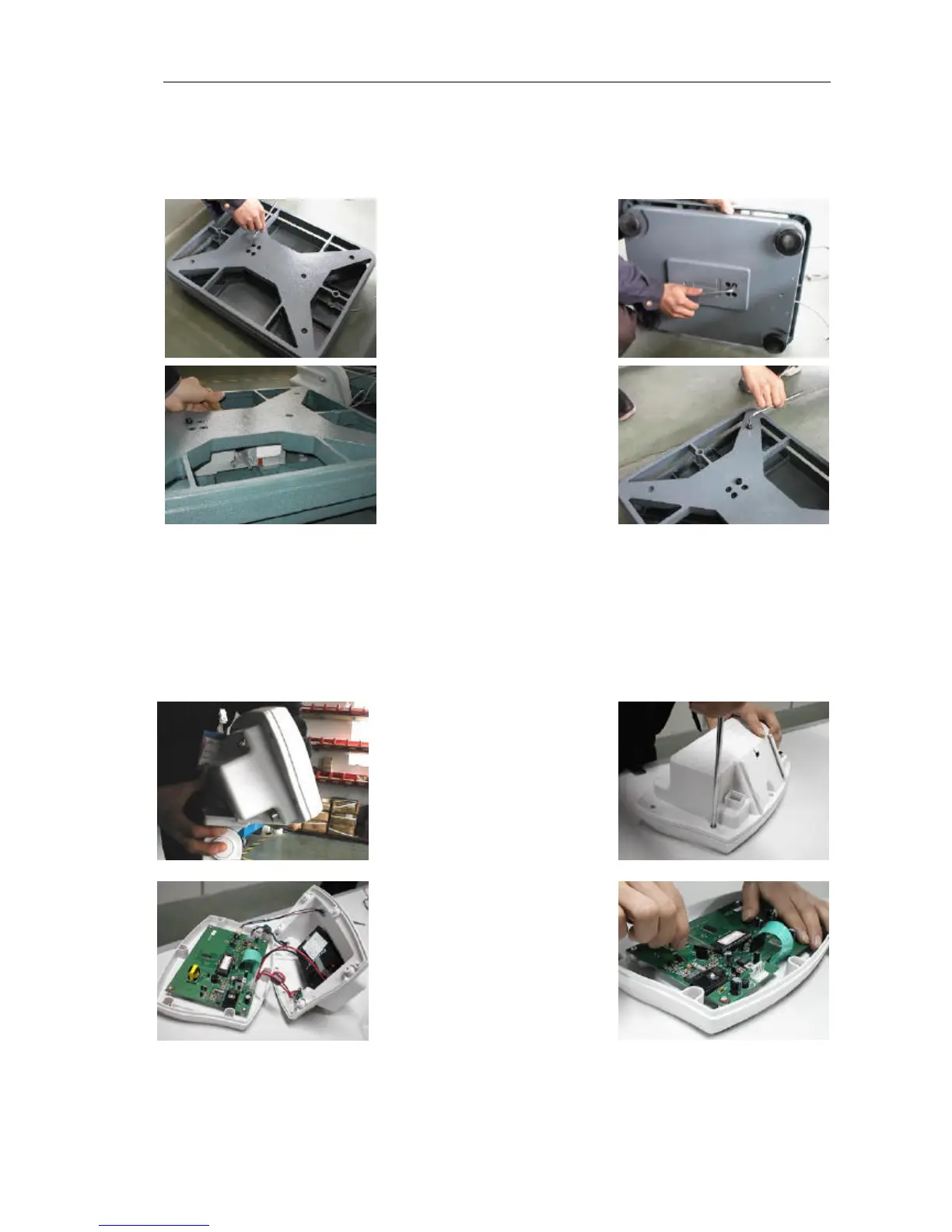
14 2 replace load cell
At first, use internal
hexagon screw driver
release 4 pcs screw from
upper bracket, remove
upper bracket, then release
4 pcs screw from bottom
bracket, by this way, you
can remove load cell now.
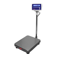
Use iron to solder cable for
load cell, remove cable
from connector, then pull
cable from pole. Bring new
load cell, let cable through
pole, solder the cable to
connector. Now, you can fix 8 pcs internal hexagon screw again (Attention: fix tight
enough as you can ). Then you can check and adjust corner and overload stop use
file and internal hexagon screw driver. After check anything, try to turn on the power
and show the internal counts, if internal counts looks OK, close the pan, change load
cell completely.
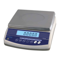
14 3 replace MPU
At first, release indicator
from indicator bracket, like
picture, then release 6 pcs
screw from back cover of
the indicator use cross srew
driver. Then, open the back
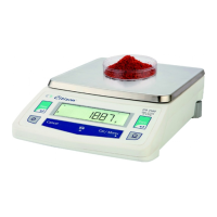
cover, pull of the connector for power (CH3.96 4P), use special IC kit or minus screw
driver to put up the MPU
from DIP40 socket
(Attention: please don’t let
the IC pin tilt), then use the
new MPU plug into DIP40
socket (Attention: please
note the gap direction), after
check anything is OK, plug the power connector (CH3.96 4P), try to turn on the
power, if scale work correctly, replace MPU completely.