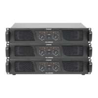
POWER
ON
OF F
PPX900 CHANNEL 1
PROT ECT
CLIP
SIGNA L
CHANNEL 2
ON
OFF
Page 3
13.
14.
15.
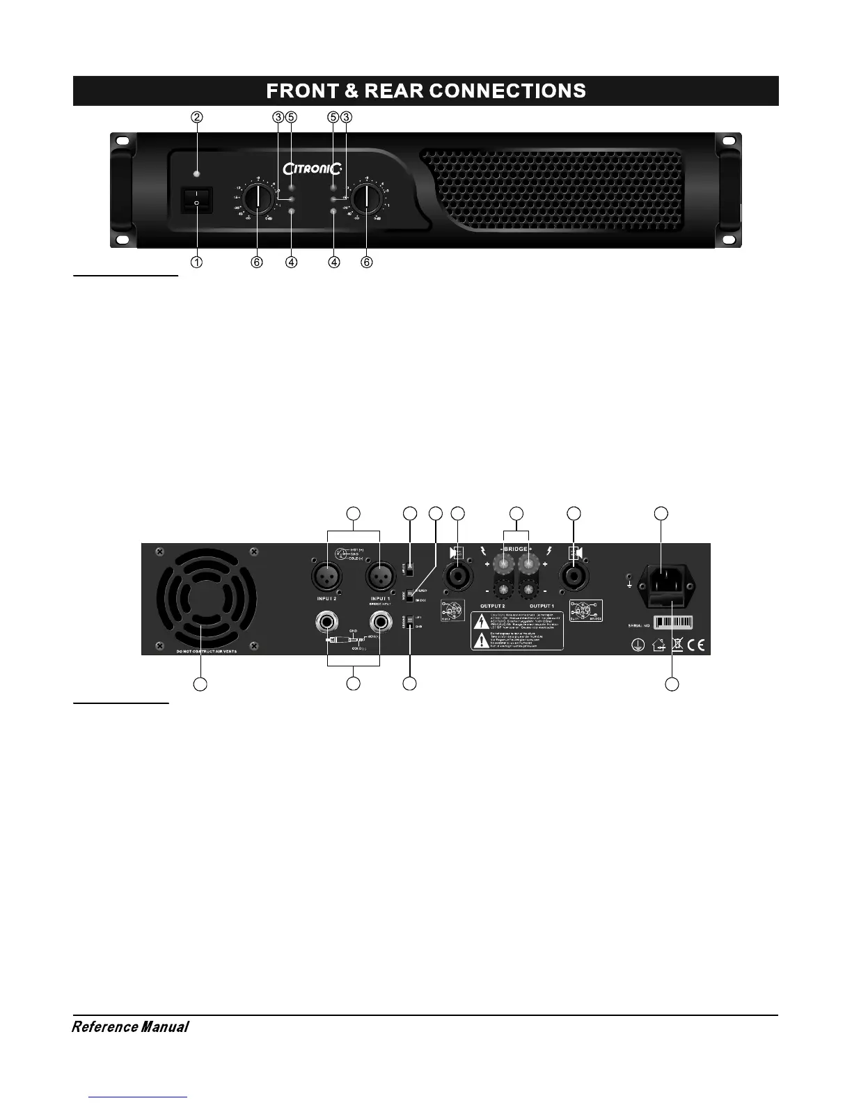
16.BUILTIU LIMITER ON/OFF SELECTOR
MODE SWITCH
BALANCED XLR INPUTS
BALANCED 6.3mm STEREO JACK INPUTS
The amplifier can use 3 different modes:stereo,bridge &
parallel (mono). Choose one of these functions:
Stereo mode: Standard left/right stereo mode.
Bridge mode: This mode combines both
double power on this channel.
Connects the signal to the left input channel and the
output level can now be adjusted with the left volume
control.
Two 3-pin female XLR input connector for connecting a
signal source (mixer etc.).
Two 6.3mm jack female input connector for connecting
a signal source (mixer etc.).
amps on one
channel which results in
13
8
10
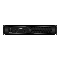
FRONT PANEL
1. POWER SWITCH
2. POWER LED INDICATORS
3. CLIP LED INDICATORS
To turn the unit ON or OFF, press the upper or lower portion of
this button. Before turning on the amplifier, check all connections
and turn down the level controls. A momentary muting is normal
when turning the amplifier on or off.
(Caution: Always turn on your power amplifier last, after all your
other connected equipment, and always turn off your power
amplifier before your other connected equipment.)
These LEDs illuminate when the power is turned "ON".
These LEDs illuminate if any section of the power amplifier s
output are within 3dB of clipping. Occasional blinking of the LEDs
are acceptable, but if they remain on more than intermittently you
should turn down either the power amplifier s level controls or
reduce the output level of the preceding component to avoid
audible distortion.
'
’
4. SIGNAL LED INDICATORS
5. PROTECT LED INDICATORS
6. LEVEL CONTROLS
These LEDs illuminate to confirm the presence of an input signal
greater than 100 mV at that channel of the amplifier
These LEDs illuminate if the power amplifier s output connection
is shorted , the load impedance is too low. Or if there is an internal
malfunction When either of these LEDs is lit up, turn OFF the power
and check the output's connection to verify that it is correct, then
turn ON the power again.
These control the level of signal coming into each channel. The
actual voltage attenuation of the amplifier is shown in dB. Turn these
controls counterclockwise if the Limit LEDs illuminate steadily
(indicating a too strong input signal).
’
7
14
REAR PANEL
7.
8. FUSE
9.
10.
11.
12.
FAN
MAINS POWER CONNECTOR
GROUND LIFT SWITCH
SPEAKER OUTPUTS NL4
BINDING POST OUTPUT JACKS
Front to rear forced airflow.
This main fuse secures the amplifier and wires against
defects. Replace this only with a fuse of same type and
value.
Allows circuit and chassis grounds to be separated in
case of problems with earth loops (hum).
Maximum load in stereo/mono mode 4 Ohm per channel.
Pin +1 & +2 = + output, Pin -1 & -2 = - output
Maximum load in stereo/mono mode 4 Ohm per channel.
Maximum load in bridge mode 8 Ohm.
15
16 11
12
11 9