tional base is installed.
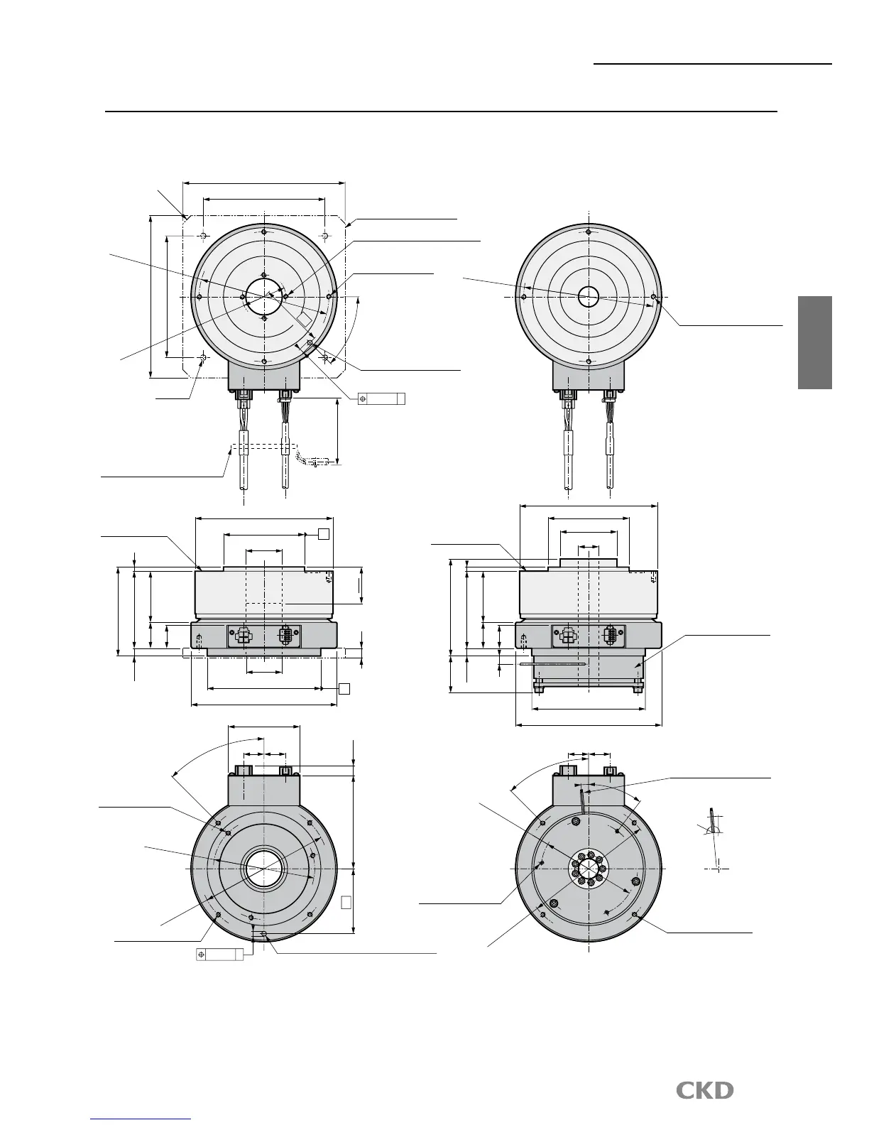
115 (11)
80
4-M6 depth 12 (straight)
(Screw valid length 9)
For mounting dial plate
P.
C.D.160
C10
150
200
4-M6 depth 12 (straight)
(Screw valid length 9)
For mounting dial plate
4-M6 depth 12 (straight)
For mounting optional electromagnetic brake
Mounting base (option)
45°
Φ6H7 depth 8 (option)
0.06
A
P.C.D.160
200
150
P.
C.D.54
80
4-Φ7
5
(9.5)
95
28.5
109.5
63 32
Rotating section
(Including hollow section)
Φ170
Φ100h7
Φ45
A
Φ180±2
Φ140h7
65
Φ44
12
B
Rotating section
(Including hollow section)
119.5
5 (9.5)
95
28.5
45.2
10
63 32
Φ170
Φ100h7
Φ70
Φ25
Φ180±2
Φ140h7
Electromagnetic brake
(Protection element attached)
88
45°
4-M6 depth 12 (straight)
P.
C.D. 160
P.
C.D.125
3-M6 depth 12 (straight)
optional electromagnetic brake
For mounting
0.06
B
4-M6 depth 12 (straight)
P.
C.D. 160
Electromagnetic brake lead wire
300 from outlet
5°
3-M5 (straight)
For electromagnetic brake
manual release
45°
Recommended value for
lead wire relief dimensions
5°
Φ140
R8
Cable bending range
(Downward bending
range is 125)
145
(Note): Fix the end of the cable
sheath when bending repeatedly.
27.3 25.6
27.3 25.6
Note 1) The origin of the actuator may differ from the dimensions shown above.
Origin can be configured randomly using the origin offset function.
 Loading...