D
GB
DX 18..27
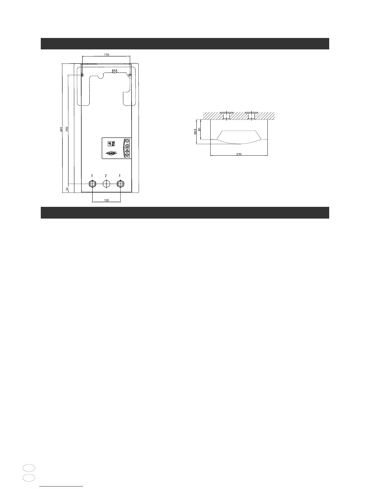
7 Abmessungen Dimensions
6
Zu beachten sind:
• VDE 0100
• EN 806-2
• Bestimmungen der örtlichen
Energie- und Wasserversorgungs-
unternehmen
• Angaben auf Typenschild
•Technische Daten
Montageort
• Der Montageort muss stets frostfrei
sein.
• Das Gerät entspricht der Schutzart
IP25 und darf gemäß VDE 0100 Teil
701 im Schutzbereich 1 installiert
werden.
• Um Wärmeverluste zu vermeiden,
sollte die Entfernung zwischen
Durchlauferhitzer und Zapfstelle
möglichst gering sein.
• Für Wartungsarbeiten sollte in der
Zuleitung ein Absperrventil installiert
werden.
• Es können Wasserleitungen aus Kupfer
oder Stahl eingesetzt werden.
Kunstoffrohre dürfen nur verwendet
The following regulations must be
observed:
• EC or national regulations
(Germany:VDE 0100 and
EN 806-2)
• The regulations of the local power
and water supply utilities
• The specifications on the rating
plate
•Technical specifications
Installation site
•The installation site must be free from
frost at all times.
•The appliance complies with pro-
tection type IP25 and may therefore
be installed in protection zone 1
according to VDE 0100 part 701.
• In order to avoid thermal losses, the
distance between the instantaneous
water heater and the tapping point
should be as small as possible.
•For maintenance work,a shut-off
valve should be installed in the supply
line.
• Copper or steel connecting pipes may
be used.Plastic pipes may only be
used if they conform to
8 Installation Installation
 Loading...