Printed in Singapore
Ilmprime
au Singapore Ilmpreso en Singapore I
~1JQJ.!Ii~.Iil!
I
~Pf.'20
2
'lJfIl
20031
11
288F0980
Clarion
InstaliationlWire Connection Guide / Manuel d'installation et de connexion
Guia de installacion/conexion de cables /
gc_/ii!i~BJJ
/
~~I/i:lH~
7~o1E
mmmmm
_
-1. BEFORE STARTING / PREPARATIFS / ANTES DE COMENZAR /
~~ZWJ
/
~~~
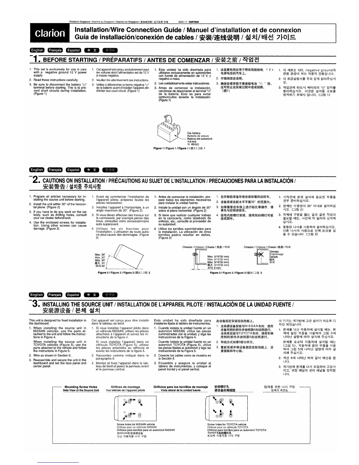
1.
This set is exclusively for use in cars
with a negative ground 12 V
power
supply.
2. Read these instructions carefully.
3. Be sure to disconnect the battery
"8"
terminal before starting. This is to pre-
vent
short circuits during installation.
(Figure 1)
1.
Cet appareil est
con<;u
exclusivement pour
les voitures dont I'alimentation est de 12 V
amasse negative.
2.
Veuillez
lire
attentivement ces instructions.
3.
Veillez
a debrancher
la
borne negative
"ICy'
de la batterie avant d'installerI'appareil
afin
d'eviter tout court-circuit. (Figure
1)
1.
Esta unidad ha sido disenada para
utilizarse exclusivamente en autom6viles
con fuente de afimentaci6n de 12
V,
Y
negativo amasa.
2.
Lea
cuidadosamente estas instrucciones.
3.
Antes de comenzar la instalaci6n,
cerci6rese de desconectar
el
terminal "8"
de la bateria. Esto es
para
evitar
cortocircuitos durante la instalaci6n.
(Figura
1)
Car
battery
Batterie
de
voiture
Baterfa
del
autom6vil
i'l$'!litl!
;>;f
~H
E~
2.1
Figure
1/
Figure
1/
Figura
1/
fIll/::J.'E/
1
1.
~~j[¥.i§lIJmfll'f*~~Jl:flHi!ti!.
1 2 v
Et!imi
Et!ffi(fJ;"I:$..t,
2.
1f~I~~~t~aJL
3.
il1D1*~1remfttr;;r-~~mEt!;l!!
"8
"
~,
i&1lTIln.It.~~~J::Ulllj:lj§.liX;~liJm,
(m1 )
1.
01
A~I.§.-e
12V,
negative
ground£1
-B~
~1:tol
£i-e
Af~~f
-B%~Ji-lcf.
2.
01
;;S11:t~~Ai~
-?£I
=f.!7-i1
~~O-j-?~AI
.2..
3.
~~-B011
'[llEAI
tlH
E-j
2.1
£1
"8"
8Af~
~2.I'Of~AI.2..
ol~.g
~j:I.g.
.iI:.§.~
tgAI'Of7I
.!f-1~HAi
~l-Icf.
(:I~
1)
mammm
_
-2.
CAUTIONS
ON
INSTALLATION
I
PRECAUTIONS
AU
SUJET
DE
L'INSTALLATION
I
PRECAUCIONES
PARA
LA
INSTALACION
I
~~~iS-1
~j:I%
~~IA~W
1.
Prepare all articles necessary for in-
stalling the source unit before starting.
2.
Install the unit within 30° of the horizon-
tal plane. (Figure 2)
3. If you have to do any work on the car
body, such as drilling holes, consult
your car dealer beforehand.
4. Use the enclosed screws for installa-
tion. Using
other
screws
can cause
damage. (Figure 3)
1.
Avant de commencer I'installation de
I'appareil pilote, preparez toutes les
pieces necessaires.
2.
Installez I'appareil aI'horizontale, a
un
angle maximum de 30°. (Figure 2)
3.
Si vous devez effectuer des travaux sur
la carrosserie, par exemple percer des
trous, consultez votre concessionnaire
auto auparavant.
4.
Utilisez
les
vis
fournies
pour
I'installation. L'utilisation de toute autre
vis peut causer des dommages. (Figure
3)
1.
Antes de comenzar la instalaci6n, pre-
pare todos los elementos necesarios
para instalar la unidad fuente.
2. Instale la unidad con
un
angulo de 30°
sobre el plano horizontal. (Figura 2)
3.
Si tiene que realizar cualquier trabajo
en la carroceria, como taladrado de
orificios, etc., consulte
al
proveedor de
su autom6vil.
4.
Utilice los tomillos suministrados para
la instalaci6n. La utilizaci6n de otros
tomillos
podria
resultar
en
danos.
(Figura 3)
1.
:fE*~fttrll~PJT~~~pJT~(fJt~aJj~,
2.
t9:~~~:fEJlf~)J<.:q;:.:q;:Mi30°
(fJmlEi*J,
3.
:!lI1*~~:fE$pjl:..tillfTt~:r:L~¥,k11=,
t~
$$t~~ti!fillj)fH~
,
4.~mi*J.~n~~,~m.(fJ~n1lT~
j§.liX;1m~,
1.
Ar~m01I
g:i:~1
~;>;10l1
:mR~
¥~~
~¥
~I:II'Of~AI.2..
2.
g:i:11-c
9-:g~21
30° OILH£
~j:I'Of~
AI.2..
(:I~
2)
3.
~f:i:~I01I
T~~
~-e
~J!f
~.g
~~ol
:mR~
[[H-e,
Af-B01I
~f
\§2-j2.f .g£I'Of
~AI.2..
4.
~*!B
LfAf~
Af%'Ofo~
~j:I'Of~AI.2.,
cfe
LfAf£1
Af%.££
~~H
~.g~
~
~
9-
~J'Erl-lcf.
(:I~
3)
Max. 30'
Max.30'
Max.
30'
~*
30'
~cH
30'
Chassis
/
Chassis
/
Chasis
/
Ji~
/
}:;fcH
Max.
5/16"(8
mm)
:
Max.
5/16"(8
mm)
:
Max.
5/16"(8
mm)
~*
5/16"(8
mm)
j;ICH
8
mm
Chassis
/
Chassis
/
Chasis
/
Ji~
/
;>;f
cH
i[
~-----
Damage
Endommage
:
Dafiado
:
t9l~
:.
__
~_
=e~
Figure 21 Figure 21 Figura
2/00
21
::J.
'E/
2
Figure 31 Figure 31 Figura
3/fIl3/
::J.
'E/
3
mammm
_
-3.
INSTALLING
THE
SOURCE
UNIT
I
INSTALLATION
DE
L'
APPAREIL
PILOTE
IINSTALACION
DE
LA
UNlOAD
FUENTE
I
~~lmti9:§
I
gj~1
~j:1
This unit is designed for fixed installation
in
the dashboard.
1.
When
installing
the
source
unit
in
NISSAN vehicles,
use
the parts at-
tached to the unit and follow the instruc-
tions in Figure 4.
When
installing
the
source
unit
in
TOYOTA vehicles (Figure
5), use the
parts attached to the vehicle and follow
the instructions in Figure
5.
2. Wire as shown in Section 6.
3.
Reassemble and secure the unit in the
dashboard and set the face panel and
center panel.
Cet appareil est congu pour etre installe
dans
Ie
tableau de
bordo
1. Si vous installez I'appareil pilote dans
un vehicule NISSAN, utilisez les pieces
attachees
aI'appareil et suivez les in-
structions de la figure
4.
Si vous installez I'appareil dans un
vehicule TOYOTA (Figure 5), utilisez
les pieces
attacMes
au vehicule et
suivez les instructions de la figure
5.
2.
Raccordez
comme
indique dans Ie
paragraphe
6.
3,
Montez et fixez I'appareil dans
Ie
tab-
leau de bord et posez
Ie
panneau avant
et
Ie
panneau central.
Esta
unidad
ha
sido
disenada
para
instalarse fijada
al
tablero de instrumentos.
1. Cuando instale la unidad fuente en un
autom6vil NISSAN, utilice las piezas
suministradas con la unidad, y siga las
instrucciones de
fa
Figura 4.
Cuando instale la unidad fuente en un
autom6vil TOYOTA (Figura
5), utilice
las piezas fijadas
al
autom6vil y siga las
instrucciones de la Figura
5.
2.
Conecte los cables como se muestra
en
la
Secci6n
6.
3.
Ensamble
y
asegure
la
unidad
al
tablero de instrumentos, y coloque el
panel frontal y
el
panel central.
Jlti9:~~iE~~~~.El1S;t&..t,
1.
3~~imliii~~~~NISSAN$at,
1rem
t9:~PJT1li~(fJii~1!f:Jf~~m4(fJt~aRill1T
,
3~~;l!l;~~~TOYOT
A$Ilt,
1reffl$W!
PJT1li~(fJii~
1!f:Jf~fi~
m5
(fJt~
aJj
ill1T
0
2.
:ffi'~JJ:tt:!!1l~6ii~;tJ'Jf5F,
3.~.~.:Jf.iii~~iE:fE.1S;t&..t,
iii
j[
Mi*.&~lllj:l
'l);t&,
01
7171-e
741711[1.1-011.:il~
~j:17f
£I.s:.~
CI
Af~
£1
~:t'ErL.J
cf.
1.
g:i:~I~
':A!H
Af~~f01I
~j:I~
[[H-e, g
:i:~1011
~~
¥~~
Af%'Ofo~
:I~
4011
LfEf'd
~~011
[q.2.f
~j:I~H
-?~AI.2..
g:i:~I~
!E.REf
Af~~f01I
~;>;I~
[[H-c
(:I~
5),
Af~~f01I
~~
¥~~
Af%
'Ofo~
:I~
5011
LfEf'd
~~011
[q.2.f
~
j:1~H
-?~AI2..
2.
-!4l{1
4011
LfEf'd
I:If2.f
~ol
tlH~~
~
L.J
cf.
3.
741711[1.1-011
g:;:;11~
CfAI
~~'Ofo~
.:il~AI
71.:il,
2.1:g
IiH'gIJ!f
-ct!E-j
IiH'gI~
:g;SJ-~
L.lcf,
Mounting Screw Holes
Side View of the Source Unit
Orifices de montage
Vue
laterale
de
I'appareil pilote
Orificios
para
los
tornillos
de
montaje
Vista lateral
de
la
unidad fuente
~.!bItHL
imii&*rrot1J:fJi!m
'Etj,"~
.!f-I~
LfAf
T~
.g"~121
~'2'!£
Screw
holes
for
NISSAN
vehicle
Orifices
pour
un
vehicule
NISSAN
Oriliaios
para
tomillos
para
un
autom6vil
NISSAN
1±NISSAN$~*,iJ.!iill:w
':;1-0
Af~;>;f-§-
qAf
T-~
Screw
holes
lor
TOYOTA
vehicle
Orilices
pour
un
vehicule
TOYOTA
Oriliaios
para
tornillos
para
un
autom6vil
TOYOTA
TOYOTA$BlJ~Ur¥L
.s=.B.Ef
Af~;>;f-§-
qAf
T-~
 Loading...