•
Instalacion
de la
unidad
fuente
en
un'
automovil
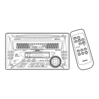
NISSAN
Note 2 1Remarque 2 1Nota 2 1
i.±:
2 1 ? 2
/
6-Spacer (Appended
to
the source unit)
6-Entretoises (Attache
aI'unite source)
r
6-Separador (Adicionado a la unidad fuente)
6-:mJt
(*:fJlI!f'tJji~)
67H.£1
::::::OlLilOIAi
(01
~t:Ilon
¥4i)
'"
@l
I 6-Flat head screw (M5 u 8)
/
@t~
'-!.
'~
(attached
to
the source unit)
o
~
®
~
6-Vis a tete plate (M5 u
8)
o
0(1
'''''::f;!
Uk
(sur I'appareil pilote)
X
y
~1iQ'
~
;-6-Tornillos
de cabeza plana (M5 u 8)
o
'l;,,'"
J"
(fijados a la unidad fuente)
, 0 '
'r9l@
0
~~
~
6-:if~!liln
(M5u8)
(im!i!l:~1l11*)
~
/'
67H.£1
'§Alo-J2.1
QAHM5U8)
~,
~
(-l'!-xiIOlI
¥~)
"
.~
\ Mounting bracket (Metal plate)
~
Etriers (plaque metallique)
Soporte de montaje (Placa metalica)
*lli!~
(~Jjit&)
EJ-AH
~~cH
(E~B)
Finisher (Appended
to
the source unit) (Note 1)
Finisseur (Attache
aI'unite source) (Remargue 1)
Placa
de
adorno (Adicionado a la unidad fuente) (Nota 1)
JE'~
(*:fJl1l11~~)
O.±:l)
om
E2.iI~
(01
~t:I1OjI
¥4i)(?
1)
•
Installation
de
I'appareil
pilote
dans
un
vehicule
NISSAN
6-Double-sided tape
(Appended to the source unit)
6-Bande a double face adhesive
(Attache
aI'unite source)
6-Cinta adhesiva por
ambas
caras
(Adicionado a la unidad fuente)
6li!tm-~iliili!t*
(*:fJl1l11Jji~)
67H£1
~~
'§~
EilolE
(01
~t:I1OjI
¥4i)
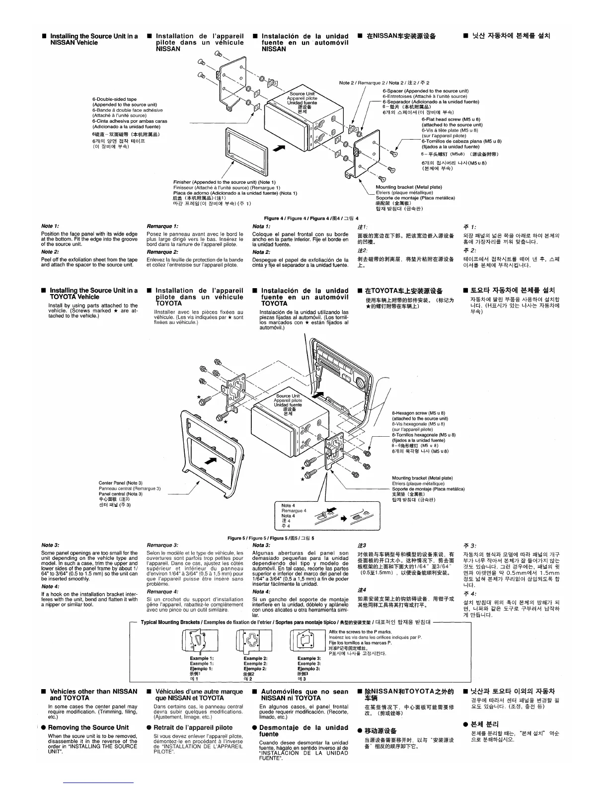
• Installing the Source Unit in a
NISSAN Vehicle
Note 1:
Position the face panel with its wide edge
at
the bottom. Fit the edge into the groove
of
the source unit.
Note
2:
Peel
off the exfoliation sheet from the tape
and
attach the spacer to the source unit.
Remarque 1:
Posez
Ie
panneau avant avec
Ie
bord
Ie
plus large dirige vers
Ie
bas. Inserez
Ie
bord dans la rainure de I'appareil pilote.
Remarque2:
Enlevez
la
feuille
de
protection
de
la bande
et
collez I'entretoise sur I'appareil pilote.
Figure
4 1
Figure
4/
Figura
4 /
1!14
/
:::J.
~ 4
Nota 1:
;'1::1:
Coloque
el
pane~
fro~tal
~on
su
borde
Wt&a<J~ii11:El'&Bo
j:~~~ii1*Aim!i!!:*
ancho
en
la parte Inferior.
FIJe
el
borde
en
Mnntilli
la unidad fuente.
R~
I"l'fi'l
0
Nota
2:
;'1::2:
Despegue
el
papel
de
exfoliacion de la
~tl~lj;Hlia<J~tl~~,
~!&:J:'i*~1l111:Eim!i!!:*
cinta y fije
el
separador a
la
unidad fuente.
_to
;;s.
1:
~I:g lIH~21
i;~g
~~
o~[!H£
o~o~
~.xjI21
~Oll
7~:gA~2.I~
7ll.'f~
'5J%L..jc~.
;;s.
2:
Ejlol~OlIAi
~~AI.§.~
[[1101
'cl!
~,
~lIjl
OIAi~
~.xjIOlI
!j!~AI~L..jc~.
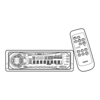
• Installing the Source Unit in a
TOYOTA Vehicle
Install by using parts attached to the
vehicle. (Screws marked
* are at-
tached
to
the vehicle.)
•
Installation
de
I'appareil
pilote
dans
un
vehicule
TOYOTA
IInstaller avec les pieces fixees
au
vehicule. (Les vis indiquees par *sont
fixees
au
vehicule.)
•
Instalacion
de
la
unidad
fuente
en
un
automovil
TOYOTA
Instalacion
de
la unidad utilizando las
piezas fijadas
al
automovil. (Los tomil-
los marcados con
* estan fijados
al
automovil.)
•
f£TOYOTA$J:~.ili9:§
1reffl$~...tIl1Hlia<J&B1**~o
(~ic;9
*a<J~nIl1Hli1:E$~...t
)
A~~~~OlI
~~
!j!~~
A~~o~O~
~~m
L-Ic~.
(HliAI7~
~H:'
qA~-E
A~~~~OlI
¥~)
Center
Panel
(Note
3)
Panneau central (Remargue
3)
Panel central (Nota
3)
J:j:l,t,'OOt&
(13)
{l!Ej
jiH~
(~3)
8-Hexagon screw (M5 u
8)
(attached to the source unit)
8-Vis hexagonale
(M5
u
8)
(sur I'appareil pilote)
Mounting bracket (Metal plate)
Elriers (plaque melallique)
~-----
Soporte de montaje (Placa metalica)
3t~m
(:;ti:Jj!t&)
'EtAH
~~
cH
(i5-~B)
Note 4
Remargue 4
~
~
~~4
P+~
~4
;;s.
3:
A~~~~21
~6j:il~
£~Oll
CCf2.f
lIH~21
7H.::r
!j!7~
Li.!f.
6to~Ai
~.xjI7~
~
~017~AIl?i-E
?;is:.
~gL..jc~.
:lE!
~-9-0l1-E,
lIH~21
%!
'21:il~
o~<;'!!'21~
Qj'
O.5mmOlI
A
i 1.5mm
~s:.
i;~'51
~.x~17~
.!f.2.I'iltol
~~£is:.~
~
L-Ic~.
;;s.
4:
~~I
'EJ-~eH
.!f121
~ol
~.xjI21
~<5H7~
£1
'21,
L..jlij~~
~g
s:..::r£
.::r!j!2~Ai
Et6to~
III
'C!-§-
L-I
cl,
i'1::4
~~*~~~...ta<J~M~.*,
fflmT~
:jt
fIi
I5J:l'$I
!ii~~:jtfJ~~
fJ.if0
i'1::3
~
••
~$~
••
~~.a<J.***,
W
.Wt&a<J*D~~o~~.~l',
.~W
t&~~a<J...tW;frrFWjd'tJ1
164"
¥,3/64
"
(0.5¥,1.5mm) ,
~:J.1i!!i!!:*~~JI!9iifIJ*~o
Remarque 3:
Selon
Ie
modele
et
Ie
type
de
vehicule,
les
ouvertures sont parfois trop petites pour
I'apparei!. Dans
ce
cas, ajustez les cotes
superieur
et
inferieur
du
panneau
d'environ 1/64" a3/64"
(0,5
a
1,5
mm)
pour
que I'appareil puisse etre insere sans
probleme,
Remarque 4:
Si
un
crochet
du
support d'installation
gene I'appareil, rabattez-Ie completement
avec une pince
ou
un
outil similaire.
Figure
5/
Figure
5/
Figura 5/1115/:J.'i!d 5
Nota 3:
Algunas
aberturas
del
panel
son
demasiado pequelias para la unidad
dependiendo
del tipo y modelo de
automOvil.
En
tal caso, recorte las partes
superior e inferior del marco del panel de
1/64" a 3/64" (0,5 a 1,5
mm)
a
fin
de poder
insertar facilmente la unidad.
Nota 4:
Si un gancho del soporte de montaje
interfiere
en
la unidad, doblelo y aplanelo
con unos alicates u otra herramienta simi-
lar.
Typical Mounting Brackets I
Exemples
de
fixation
de
I'etrier I
Soprtes
para
montaje
tipico I
~m!Il(Ji:~Ji~
I
eHli~
8
'MAH~
'EJ-~
eH
------,
Note 3:
Some panel openings
are
too small for the
unit depending
on
the vehicle type and
model.
In
such a case, trim the upper and
lower sides of the panel frame by about 1/
64"
to 3/64" (0.5
to
1.5
mm)
so
the unit
can
be
inserted smoothly.
Note
4:
If
a hook
on
the installation bracket inter-
feres with the unit, bend and flatten it with
a nipper or similar tool.
Example 1:
Exemple 1:
Ejemplo 1:
jf-fJiJl
0111
Example 2:
Exemple2:
Ejemplo2:
jf-1JIJ2
01/2
[ill[]
Affix the screws
to
the P marks.
h·
Inserez les vis dans les orifices indiques par
P,
L-J Fije los tomillos a las marcas
P.
••
j(1*Pi2~~)'E~~o
PiEAIOIl
qAf~
jl~AI~cf.
Example 3:
Exemple3:
Ejemplo3:
jf-fJ13
0113
• Vehicles
other
than NISSAN
and TOYOTA
In
some cases the center panel may
require modification. (Trimming, filing,
etc.)
I • Removing the Source Unit
When
the
soure unit is
to
be
removed,
disassemble it in the reverse of the
order
in
"INSTALLING THE SOURCE
UNIT".
• Vehicules d'une autre marque
que
NISSAN
et
TOYOTA
Dans certains cas,
Ie
panneau central
devra subir quelques modifications.
(Ajustement, limage, etc.)
• Retrait de I'appareil pilote
Si
vous devez enlever !'appareil pilote,
demontez-Ie
en
procedant aI'inverse
de "INSTALLATION
DE
L'APPAREIL
PILOTE".
•
Automoviles
que
no
sean
NISSAN ni TOYOTA
En
algunos casos,
el
panel frontal
puede requerir modificacion. (Recorte,
limado, etc.)
•
Desmontaje
de la
unidad
fuente
Cuando desee desmontar la unidad
fuente, hagalo,en senti
do
inverso
al
de
"INSTALACION
DE
LA UNlOAD
FUENTE".
•
~NISSAN~TOYOTAZ~~aq
$$PIj
1:E
•••
~~,
~~Wt&~.~~.
~o
(.~lili~)
•
3~ilii§
~im!.*~~.*",
~~.*~im!.
*"
tf:l.&a<JJI!9iJ¥lfPl''t::
0
•
':A!~j1J-
~.2E~
012/21
;q~~~
~-9-0l1
CCf2.~Ai
{l]Ej
1I)j~~
~~y
-m
Rs:.
~lgL-lc~.
(3':~,
.g.~
%)
~.xjl~
~2.IY
[[H-E,
"~.xjl
~~I"
'2'l"i?
££
~<5Ho~~AI.2..
 Loading...