EasyManua.ls Logo

Clarion APA2103 - Setting Gain

Clarion APA2103
9 pages
Print Icon
To Next Page IconTo Next Page
To Previous Page IconTo Previous Page
Loading...
•
When
making
connections,
be
sure
that
eac
h
co
nnection
is
clean
and
secure
. Insulate
final
connections
with
electrical
tape
or
shrink
tubing
.
Failure
to
do
so
may
damage
your
equipment.
+ A
secure,
clean
ground
connection
is
critical
to
the
performance of
your
Clarion
car
audio
amplifier.
Use
the
shortest
ground
wire
possible
to
minimize
resistance
and
avoid
noise
problems.
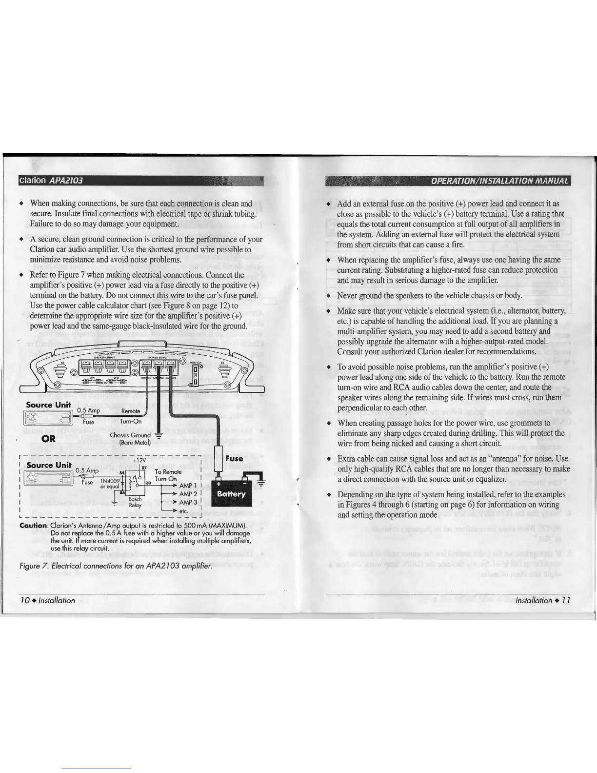
+
Refer
to
Figure
7
when
making
electrical
connections.
Connect
the
amplifier's
positive
(+)power
lead
via
a
fuse
directly
to
the
positive
( +)
terminal
on
the
battery
.
Do
not
connect
this
wire
to
the
car's
fu
se
panel.
Use
the
power
cable
calculator
chart
(see
Figure
8
on
page
12
)
to
determine
the
appropriate
wire
size
for
the
amplifier
's
positive
(
+)
power
lead
and
the
same-gauge
black-insulated
wire
for
the
ground.
Source
Unit
0 5 Amp Remote
J
g;
al
l==l·
:n:
Fu
=se===T=ur=n=-O=n,;7
OR
Chassis Ground
(Ba
re Metal)
r - - - - - - - - - - - - - - - - - -
-:-
- - - -
...,
Fuse
• +12V I
I Source
Umt
87
I I
0
ol
0.5
Amp ·
85
To
Remote I
I
-~
B Fuse
1N4
009 -
30
Turn
-
On
I
I or
equal
AMP 1 I
I
86
AMP 2 I
I
_
Bosch
AMP
3
I
-
Reloy
I
I
*·
L-----------------------J
Caution:
Clarion's
Antenna/Amp
output
is
restricted
to
500
mA
(MAXIMUM).
Do not replace the 0.5 A
fuse
with a higher value or you will damage
the unit.
ff
more current
is
required when installing multiple amplifiers,
use
this relay circuit.
Figure
7.
Electrical
connections
for
an
APA2103 amplifier.
10 • Installation
+
Add
an
external
fu
se
on
the
positive ( +)
power
lead
and
connect
it
as
close
as
possible
to
the vehicle's (+)battery
terminal.
Use
a
rating
th
at
equals
the
total
cune
nt
consumption
at
full
outp
ut
of a
ll
amplifie
rs
in
the
syste
m.
Adding
an
external
fu
se
will
protect
the
elect
rical
sys
tem
from
s
hort
circuits
that
can
cause
a
fire.
+
When
replacing
the
a
mpl
ifier's
fuse,
al
ways
u
se
one
h
av
ing
the
same
cmTent
rating
. Substit
ut
ing
a
higher-rated
fuse
can
reduce
protection
and
may
result
in
se
riou
s
damage
to
the
amplifier.
+
Never
gro
und
the
speakers
to
the
vehicle
cha
ss
is
or
body.
+
Make
sure
that
yo
ur
ve
hicle
's
electrical
system
(i
.
e.,
alternator,
battery,
etc.)
is
capable
of
handlin
g
the
additional l
oad.
If
you
are
planning
a
multi-amplifier
sys
tem
,
you
may
need
to
add
a
second
battery
and
po
ssibly
upg
rade
the
a
lt
ernato
r
with
a
hi
gh
er
-output
-rated
model.
Consult
your
aut
horized
Clarion
dealer
for
recommendation
s.
+
To
avoid
po
ssi
ble
noise
problems
, run
the
amplifier's positive (
+)
power
lead
along
one
side
of
the
vehicle
to
the
battery
.
Run
th
e re
mote
turn-on
wire
and
RCA
a
udi
o
cables
down
the
center,
and
route
the
s
peak
er
w
ir
es
along
the
remaining
side.
If
wires
mu
st
cross,
run
th
em
perpendicular
to
each
other.
+
When
creating
passage
hol
es
for
the
power
wire,
use
gro
mm
ets
to
eliminate any s
harp
edges
created
during
diilling.
This
will
protect
the
w
ir
e
from
being
nicked
and
cau
s
ing
a
short
circuit.
+
Extra
ca
ble
can
cause
signa
l
lo
ss
and
act
as
an
"antenna"
for
noise.
Use
only
high-quality
RCA
ca
ble
s
that
are
no
lon
ger
than
necessary
to
make
a
di
rect
connection
with
the
source
unit
or
eq
u
alizer.
+
Depending
on
the
type
of
sys
t
em
being
installed, refer
to
the
examples
in
Figures
4
through
6
(s
t
arting
on
page
6)
for
information
on
wiring
and
setting
the
operation
mode.
Installation •
11