I
wners
anua
c
INPUT
CONNECTIONS
AND
AUDIO
CONTROL
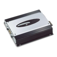
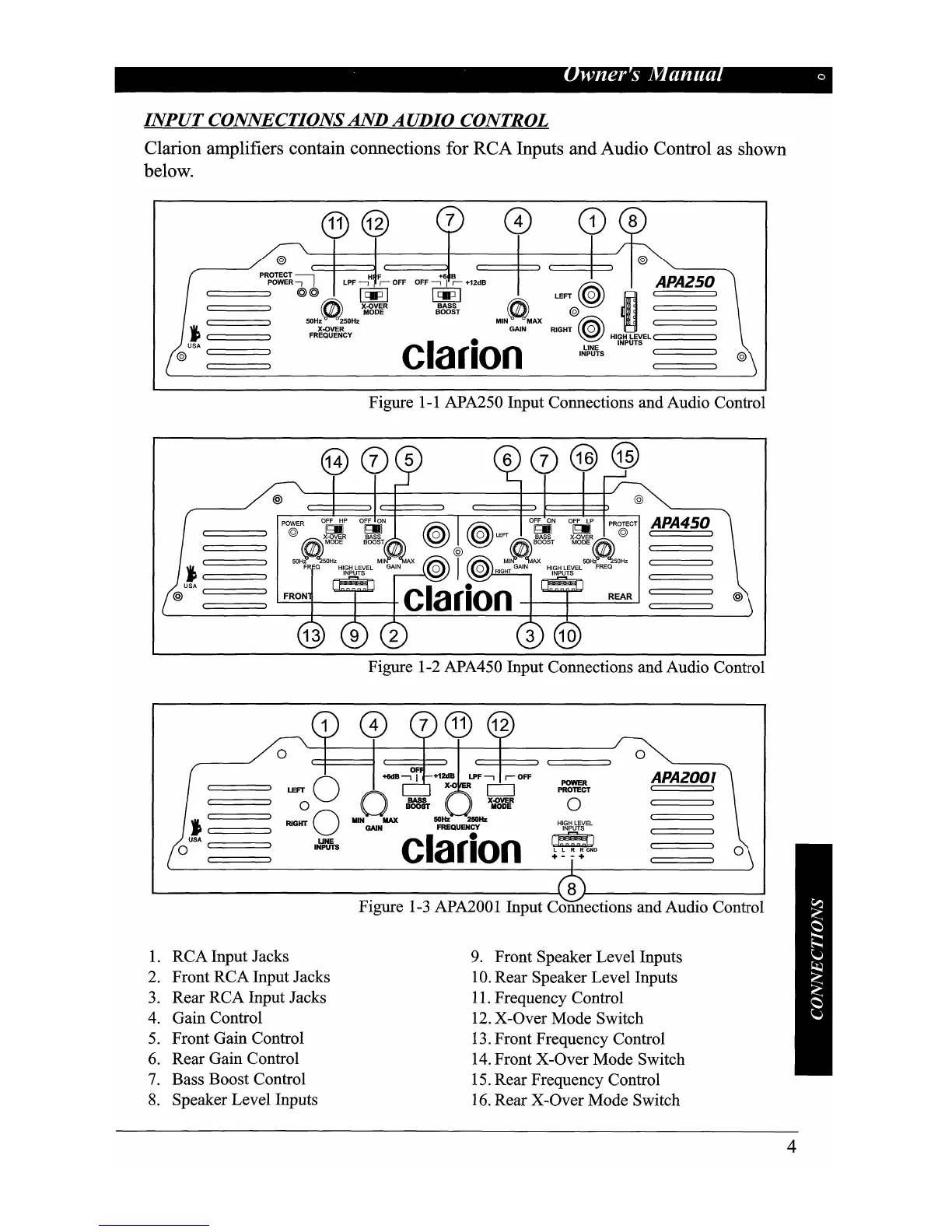
Clarion amplifiers contain connections for RCA Inputs and Audio Control as shown
below.
@
p~~
LPF~OFF
LEFT@@
~
••
APA250
C=====:::J
~
~"%'b~R
~
~
.
c=======>
50Hz 250Hz
MIN
MAX
~
I
j
C:
=======>
FR~<?.Y€:CY
GAIN RIGHT
'@HIGHLEVEL
C.
======:l
@USA
clarion
I~~S
INPUTS
C:=====::J
@
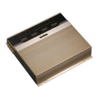
Figure
1-1
APA250 Input Connections and Audio Control
j
:C:=====:::J
@
USA
C:=====::J
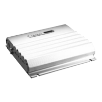
APA450
I
@
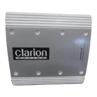
Figure 1-2 APA450 Input Connections and Audio Control
L..------------------
----\8~-------------I
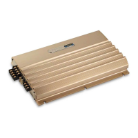
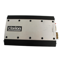
Figure
1-3
APA2001 Input Connections and Audio Control
9.
Front Speaker Level Inputs
10.
Rear Speaker Level Inputs
11.
Frequency Control
12.
X-Over Mode Switch
13.
Front Frequency Control
14.
Front X-Over Mode Switch
15.
Rear Frequency Control
16.
Rear X-Over Mode Switch
o
APA2001
o
o
POWER
PROTECT
HIGH LEVEL
IJ~NeT:QD
+ - - +
o
~O
O
....
~
RIGHT
0
MIN
MAX 50Hz 250Hz
~
~N
Clarion
o
J
c=::
===:::=l
o
USA
C=====::J
1.
RCA Input Jacks
2.
Front RCA Input Jacks
3.
Rear RCA Input Jacks
4.
Gain Control
5.
Front Gain Control
6.
Rear Gain Control
7.
Bass Boost Control
8.
Speaker Level Inputs
4
 Loading...