- M2-929-0374-81
1
CD-PWB-ASSY
5
2
3
4
SIDE-P-ASSY-F
Switches
SW-LINK
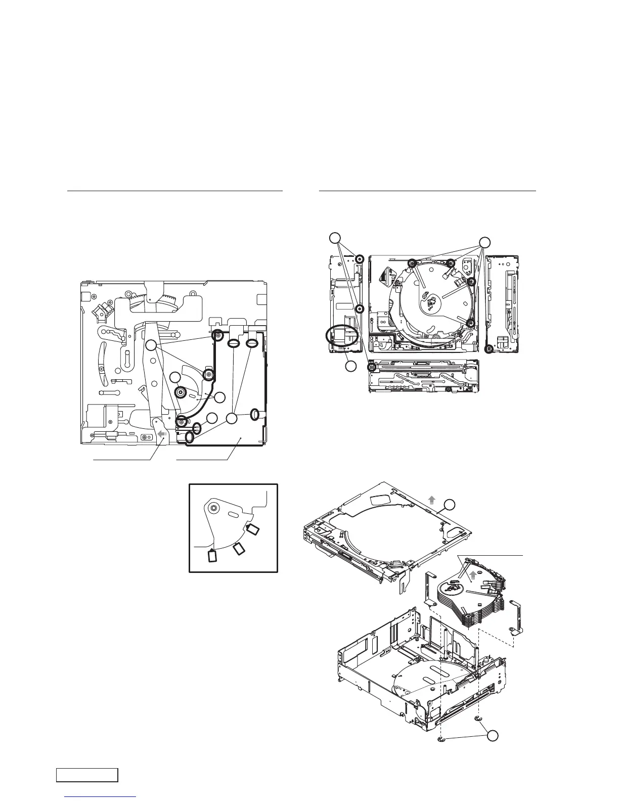
DISASSEMBLY
How to remove "CD-PWB-ASSY"
1. Add +5V to "U+" terminal of UD-MOTOR-ASSY,then
SIDE-P-ASSY-F moves outside of CD-PWB.
2. Release four FPCs.
3. Remove three screws
4. Remove the washer.
5. Remove SW-H-PLATE and SW-LINK, and remove CD-
PWB-ASSY.
* When assembling, match
SW LINK to three switches.
How to remove "DISCHOLDER UNIT"
1. Remove eight screws.
2. Remove the FPC.
3. Remove UPPER UNIT ASSY.
4. Remove two C-RINGs, and remove DISCHOLDER
UNIT.
1
1
2
3
DISCHOLDER UNIT
4
pin 81: TEST 3 :IN: For the test.
pin 82: TEST 4 :IN: For the test.
pin 83: REQ O : O : Transmit request signal output.
pin 84: I2C SDA :I/O:I2C serial data input/output.
pin 85: I2C SCL :I/O: I2C serial clock input/output.
pin 86: ACC DET :IN: ACC detection signal input.
pin 87: NU : - : Not in use.
pin 88: SW 1 :IN: The switch signal input.
pin 89: VCC : - : Positive voltage supply.
pin 90: SW 2 :IN: The switch signal input.
pin 91: VSS : - : Negative voltage supply.
pin 92: SW 3 :IN : The switch signal input.
pin 93: SW 4 :IN : The switch signal input.
pin 94: NU : - : Not in use.
pin 95: PT 1 :IN : The photo sensor signal input.
pin 96: PT 2 :IN : The photo sensor signal input.
pin 97: PT 3 :IN : The photo sensor signal input.
pin 98: PT 4 :IN : The photo sensor signal input.
pin 99: PT 5 :IN : The photo sensor signal input.
pin100: Vref H : - : Reference voltage.
 Loading...