Section 3. Know Your Truck
3.5
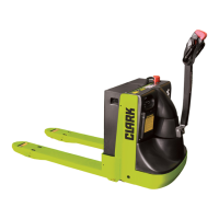
Maintenance Component Location
System Description
Control Handle
• Controls travel direction and speed, lift and lower, horn, braking
and steering.
• Butterytypespeedcontrolforleftorrighthandoperation.
• Brake application at uppermost and lowered position.
• Safety reversing switch on end of control handle.
• 180° rotation for maneuverability.
Drive Unit
• Double reduction gears
• Totally enclosed with lubricating oil bath
• Horizontal mount drive motor
• One nut drive wheel mounting for simple removal and replace-
ment.
Brake
• Double acting.
• Spring applied - cam released.
• Drum and shoe type.
• Easy service accessibility.
Electrical
• 24 volt electrical system
• (WP 30 only) Solid state Seperatly Excited Transistor control features
cool and quiet operation, cold switching for increased contactor tip
life,andinnitelyvariabletravelspeedcontrol.
Hydraulic system
• Integral motor - pump - reservoir assembly features a control valve
and pressure relief valve for controlled lowering and system overload
protection.
Frame and Forks
• Formed steel plate with bar steel reinforcements.
• Square section solid steel pull rods.
• Lift linkage easily greasable at all pivot points.
• Lift linkage provides 5.2" of lift.
• Optional Spring loaded stability casters