13
Driveshaft Alignment.
The following steps describe the proper way to check alignment. A small pocket scale or ruler with millimeter
markings is recommended to make all measurements. (Clarke Pocket Scale part number C125781)
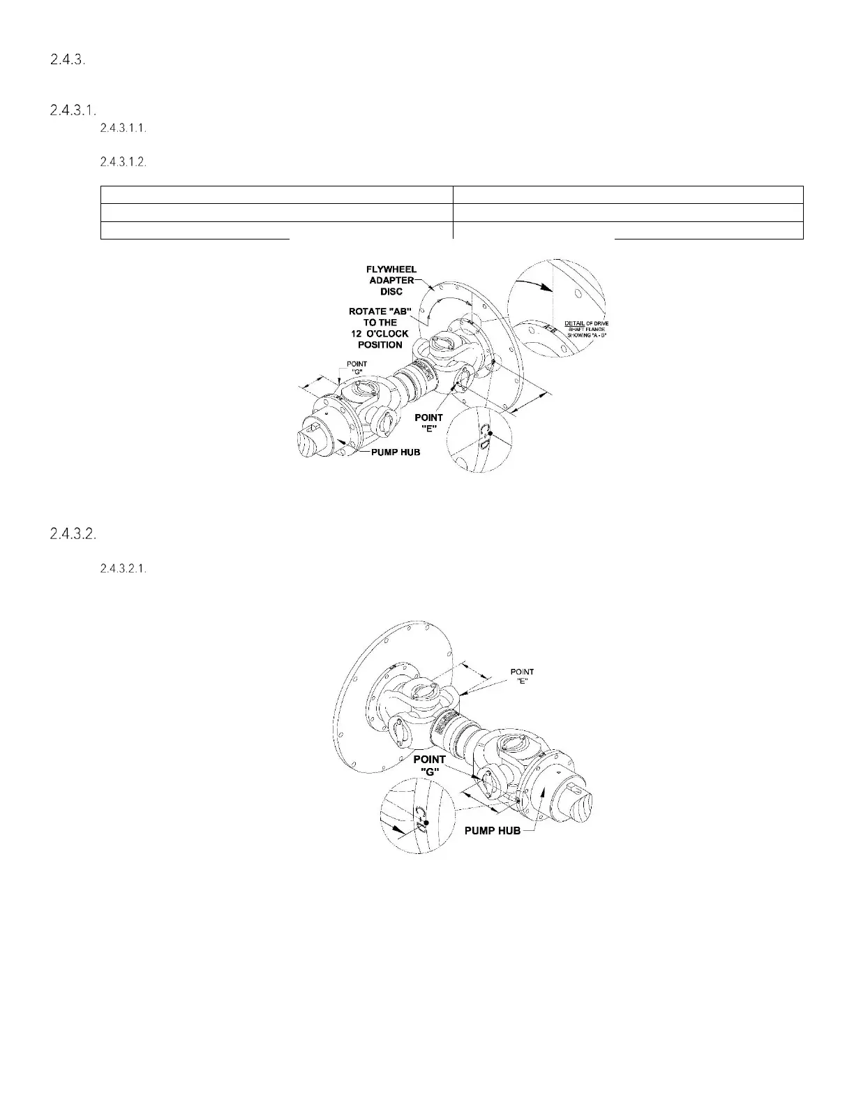
(Step A) To check the Horizontal Parallel Offset, the driveshaft must be in the proper orientation.
Rotate the shaft so the reference “AB” on the flywheel adapter disc or the circumference of the drive
shaft flange (against the flywheel adapter disc) is in the 12 o’clock position shown on figure #2-3.
Measure from the face of the flywheel adapter disc to point E. (Point E is on the bearing bore as shown
in Figure #2-3). This measurement must:
Figure 2-3
(Step B) With the driveshaft in the same orientation as the previous step (Step A), check the Horizontal Angular
alignment of the shafts.
Measure from the mating surface of the companion hub to point G shown on figure #2-4. (Point G is the
furthermost point on the bearing bore). This measurement must be equal to the measurement at point
E + 0.5 mm.
Figure 2-4