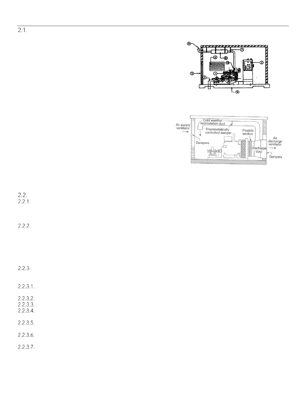
1. Pump/Engine set
2. Main Pump Controller
3. Pump discharge
4. Air louver
5. Entrance door with air louver
6. Exhaust silencer
7. Exhaust system supports
8. Exhaust outlet pipe
9. Concrete base
10. Exhaust flexible connection joint/pipe
11. Air Discharge Duct from Radiator
NOTE: For radiator cooled engines, the
total air supply path to the pump room,
which includes any louvers or dampers,
shall not restrict the flow of the air more
than 0.2” (5.1mm) water column.
Likewise, the air discharge path, which
includes any louvers, dampers, or
ducting, shall not restrict the flow of air
more than 0.3” (7.6mm) water column.
Engine Storage
Coolant System
Completely fill the cooling system before storage. (It is common for Clarke to ship the engine pre-filled with
coolant.) Clarke Coolant (part # C054129).The only acceptable substitute is COOL-GARD II part number
TY26575. Warranty is contingent on utilizing the indicated coolant.
Storage less than 1 year
Storing engines requires special attention. Clarke engines, as prepared for shipment, may be stored for a
minimum of one year. During this period, they should be stored indoors in a dry environment. Protective
coverings are recommended provided they are arranged to allow for air circulation. The stored engine should
be inspected periodically for obvious conditions such as standing water, part theft, excess dirt buildup or any
other condition that may be detrimental to the engine or components. Any such conditions found must be
corrected immediately.
Extended Storage Maintenance Procedure
After a one-year storage period or if the engine is being taken out of service for more than 6 months, additional
preservation service must be performed as follows:
Clean the engine of any dirt, rust, grease, and oil. Inspect the exterior. Paint areas that contain paint damage
with a good quality paint.
Remove dirt from the air cleaners. Check all seals, gaskets, and the filter element for damage.
Apply lubricant to all points in this Operation and Maintenance Manual, "Maintenance Interval Schedule".
Drain the crankcase oil. Replace the crankcase oil and change the oil filters. For the proper procedure, refer to
this Operation and Maintenance Manual.
If the engine is equipped with an air starting motor, fill the reservoir with the following mixture: 50 percent
volatile corrosion inhibitor oil (VCI oil) and 50 percent engine oil.
Add VCI oil to the crankcase oil. The volume of VCI oil in the crankcase oil should be 3 to 4 percent.
Note: If the engine crankcase is full, drain enough engine oil so the mixture can be added.
Remove the air filter elements. Turn the engine at cranking speed with the throttle control in FUEL OFF position.
Use a sprayer to add a mixture of 50 percent VCI oil and 50 percent engine oil into the air inlet or turbocharger
inlet. Note: The mixture of VCI oil can be added to the inlet by removing the plug for checking turbocharger