43
The over speed shut down set point is factory set, programmed into the ECM, and not field adjustable.
Caution: Do not attempt to overspeed the engine to verify overspeed shutdown.
Field Simulation of Pump Controller Alarms
Alarm 1: Overspeed Shutdown. Follow section 8.3
Alarm 2: Low Oil Pressure - With the engine running, lift the low oil pressure switch. (Note: There is no engine
mounted Low Oil Pressure switch to jumper across).
Alarm 3: High Engine Coolant Temperature - With the engine running, lift high water temperature switch. It
may take up to 5 minutes to activate the alarm. (Note: There is no engine mounted High Coolant Temperature
switch to jumper across).
Alarm 4: Over crank (Fail to Start). Disconnect the BASE module by unplugging the 26-pin connector. Lift and
hold the Overspeed reset switch, located on the internal verification switch plate, for 5 seconds prior to
initiating the 6 crank cycles from the pump controller. The switch can be released, after the 5 second hold, for
the duration of the test. NEVER shut off the fuel supply to the engine to prevent it from starting. Shutting off the
fuel supply will cause an air lock condition in the fuel system and possibly cause fuel system component
damage. Once the fire pump controller has attempted to start the engine 6 times, reconnect the 26-pin
connector to the BASE. NOTE: Ensure that the connector latches into place. Place both ECMs back into service
by moving the ECM Selector Switch “up” to the Alternate ECM position and waiting for the 6-up display to
repopulate with numbers. Then push the ECM Selector Switch “down” to return to Primary ECM operation.
Verify that the 6-up display is populated with numbers and that no parameter reads “No Data”.
Alarm 5: Low Engine Coolant Temperature - With engine at rest, lift low coolant temperature switch for 25
seconds.
Alarm 6: ECM Warning - Lift the OVERSPEED RESET SWITCH for 2 minutes with engine not running to verify
ECM Warning Alarm; note engine will automatically switch to alternate ECM.
Alarm 6: ECM Failure - After ECM Warning Alarm has been tested, continue lifting OVERSPEED RESET SWITCH
for additional 2 minutes with engine not running to verify ECM Failure Alarm. After activation of both ECM
Warning and Failure Alarms, activate the ECM Failure Reset Switch inside the engine control panel.
Battery Requirements
All Clarke engine models require 8D batteries, as sized per SAE J537 and NFPA20. The battery should meet
the following criteria:
Cold Cranking Amps (CCA @ 0°F): 1200
Reserve Capacity (minutes): 430
Refer to Clarke drawing (see Page 5) for additional information on Clarke supplied batteries.
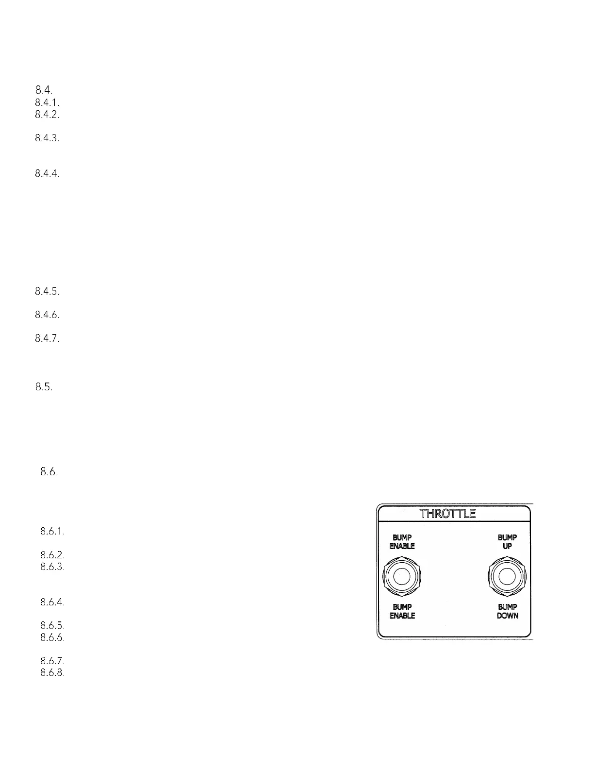
Engine Speed Adjustment
All governor and speed control functions are programmed
into each ECM at the factory. During Start-Up Inspection,
some minor speed adjustment may be required. To adjust
the speed of the engine:
Start the engine by following the “To Start Engine” Procedure
in this manual.
Let the engine warm-up. Open engine gauge panel.
While observing the tachometer, lift and hold the speed
change enable switch. Toggle speed adjustment switch up
or down to increase or reduce speed. (Refer to Figure # 8-2).
Stop engine by following “To Stop Engine” Procedure in this
manual.
Switch to Alternate ECM and repeat steps A through D.
Stop engine by following “To Stop Engine” Procedure in this
manual.
Switch back to Primary ECM.
Close panel door, replace door retaining screws.