38
Raw Water Outlet
NOTE: NFPA 20 does allow for the heat exchanger outlet flow to be returned to a suction reservoir. This makes
it very difficult to measure the flowrate. When discharging to a suction reservoir, NFPA provides additional
requirements:
A visual flow indicator and temperature indicator are installed in the discharge (waste outlet) piping.
When waste outlet piping is longer than 15ft (4.6m) and / or the outlet discharges are more than 4ft
(1.2M) higher than the heat exchanger, the pipe size increased by at least one size.
Verify that when the correct flow rate is achieved that the inlet pressure to the heat exchanger (or CAC)
does not exceed 60psi (4bar)
If you have such an installation, it is recommended that you run the engine for a period of time at firepump
150% flow and confirm the visual flow indicator is showing water flow, the temperature rise is not excessive
(usually no more than 40F (4.5C) over ambient raw water temperature) and the engine is showing no signs of
overheating.
Raw Water Quality, Strainers and Deterioration of Heat Exchanger (or CAC)
Over time, as the heat exchanger (or CAC) begins to plug and foul, this pressure will rise and the flow will
diminish which could mean that the heat exchanger (or CAC) may have to be serviced or replaced. (For NSR
heat exchangers, reference section 9.6 for cleaning procedure.)
It can be not stressed enough how important it is to keep the wye strainers within the cooling loop clean: Most
engine failures occur due to plugged cooling loop strainers! If the raw water supply has debris in it (leaves,
stones, etc) as the strainer accumulates more debris (that will not pass thru it), the flowrate will continue to
diminish which will eventually starve the engine of adequate cooling water flow which will lead to engine
overheat and catastrophic engine failure. When this occurs you have no fire protection! Clarke recommends
that after the initial engine commissioning and also prior to each weekly exercise of the engine / fire pump set,
both strainers be removed and cleaned and then re-installed before starting the engine.
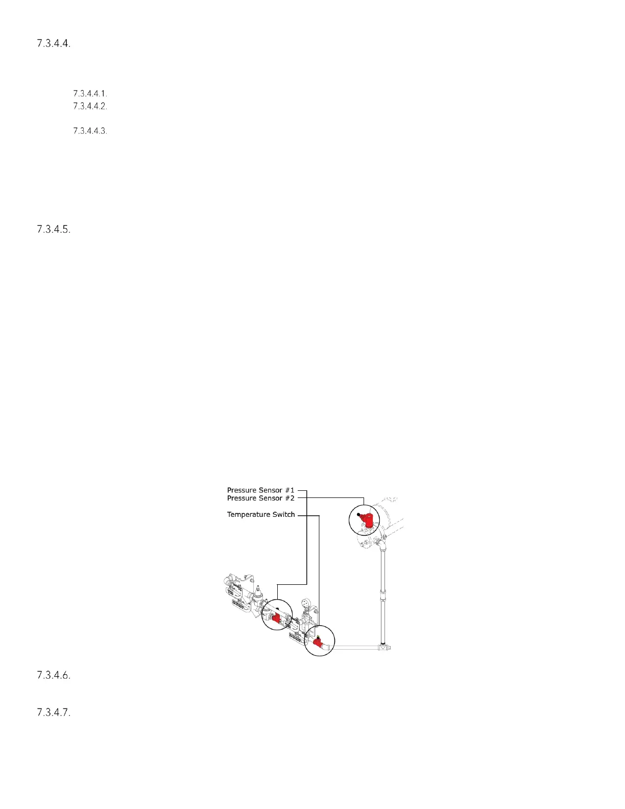
Clarke engines are equipped with an alarm that is meant to signal diminished raw water flow rate (terminal 311),
possibly due to clogged raw water strainers in the cooling loop. Refer to Figure #7-5 for location of sensors. A
circuit board located near the front of the cooling loop monitors differential pressure between the two sensors
and will send an alarm to the controller if a low water flow condition exists.
Additionally, a raw water temperature switch will send an alarm (terminal 310) when temperature of the water
exceeds 105°F (41° C). Refer to Figure #7-5 for location of switch. If either of these alarms are active, it
indicates that the cooling system’s capability may be compromised.
Figure 7-5
Backflow Preventers
NFPA20 allows for the use of backflow preventers in the Automatic and Manual flow line of the cooling loop as
required by local code. For specific application information contact factory.
Raw Water Outlet Temperature