11
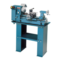
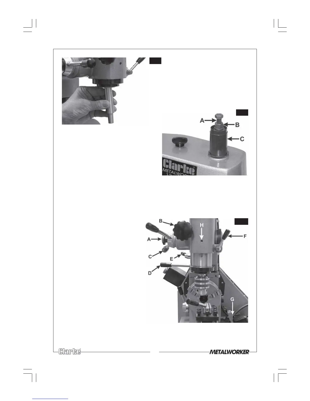
.....then screw the Draw Bar (‘A’Fig.9),
down through the spindle and into
the arbor - fully.
Secure by tightening the locknut (‘B’
Fig.9).
• The chuck may now be located on the morse tapered arbor. Tap home using a
block of wood ONLY.
• Screw the Spindle Cover (‘C’ Fig.9) into the pulley cover and place the cap on top
• Screw the two handles (‘C’ Fig.10) into the spindle feed hub and tighten.
NOTE: A locking lever (‘E’ Fig.10) secures the Mill Head. By slackening the lever, the
Mill Head may be rotated about the Headstock - convenient for moving it out of
the way during turning operations.
Fig.9
Fig.10
A .... Spindle Feed Dog Clutch
B ..... Spindle Microfeed Handle
C .... Spindle Feed Handle
D ..... Mill Head Raising Lever
E ..... Mill Head Locking Lever
F ..... Spindle Locking Lever
G .... Drive Belt Adjuster
H ..... Spindle Sleeve Locating Peg
Fig.8
• Slide the Arbor into the spindle
and push home - fully (Fig.8)......