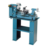
12
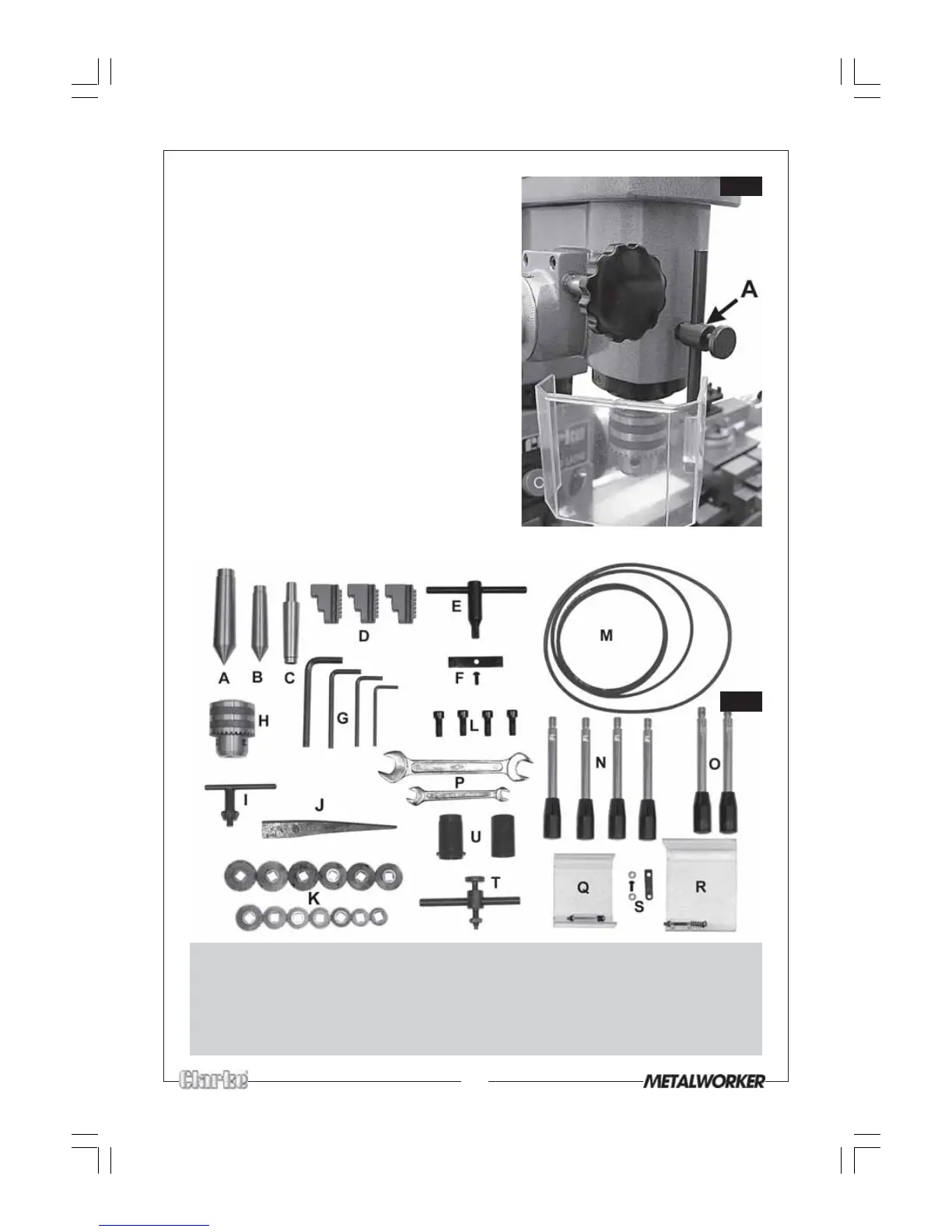
• Fit the Chuck Guard as follows:
a. Unscrew and remove the spindle
sleeve locating peg from the front of
the mill head shown at ‘H’, Fig. 10.
b. Screw the Guard Support assembly
(‘A’ Fig. 11) - to be found in the box of
loose parts, into the hole vacated by the
locating peg, until it binds. Back off
approx. one quarter of a turn and lock in
place with the locknut. The support
bar should be perpendicular, as shown.
c. The screw attached to the guard should
be screwed into the underside of the
support rod and locked in place.
The guard may be raised or lowered on
the bar as required.
The following is a list of items to be found in
the box of loose parts
Fig.11
Loose Items
Fig.12
A Centre B. Tailstock Centre C. Arbor
D. External Jaws F. Mill Head Cover Clamp w/screw E. 3-Jaw Chuck Key
G. Set (4) Hex. Wrenches H. Drill Chuck I. Drill Chuck Key
J. Drift K. Set (13) Gear Wheels L. 4xHex. Skt. Head Screws
M. 4x Drive Belts N. 4x Levers O. 2x Levers (large)
P. Spanners. 8,10,17 & 19mm Q. Drill Chuck Guard R. 3-Jaw Chuck Guard
S. 3-Jaw Chuck Guard Fittings T. 3-Jaw Chuck Guard Support U. Spindle Cover & Cap