24
SETTINGS AND ADJUSTMENTS
Occasionally, it may be necessary to readjust various components in order to maintain
optimum performance. The adjustments that may be performed are as follows:
A. Compound Slide Adjustments
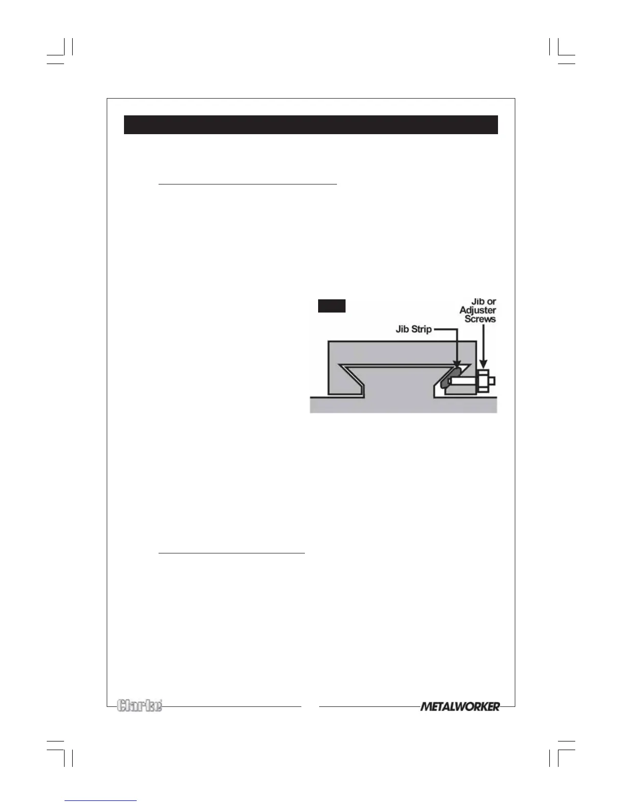
The cross-slide is mounted on a dovetail slide, as shown in Fig. 23. Between the
sloping surfaces on one side of the dovetail, a ‘jib strip’ is inserted, which may be
tightened against the dovetail under the influence of adjuster, or ’jib’ screws,
mounted along its’ length.
The jib screws are to be found on the left hand side of the slide. In time, wear will
occur on the mating surfaces resulting in a ‘sloppiness’ of action.
To adjust the jib strip, to account for wear and ensure the slide moves evenly and
smoothly, proceed as follows:
1. Slacken off all lock nuts and screw
in the jib screws evenly, i.e. use the
same torque for each screw. The
slide should be held firmly. Test by
trying to turn the handle, but do
not force it.
2. Screw out each jib screw by one
quarter of a turn ONLY, and nip up
the lock nuts
3. Test again, by turning the handle. The
movement should be even and smooth along its complete length.
4. If the movement is too slack, screw all adjusters ‘in’ by one eighth of a turn, and
retry. Similarly, if the movement is too stiff, screw ‘out’ the adjusters by one
eighth of a turn until the correct adjustment is attained.
5 Tighten all lock nuts taking care to ensure you do not move the jib screws whilst
doing so.
6. When completed, retract the slide fully and apply oil to all mating surfaces and
the feed screw thread, then wind the slide back to its normal position.
B. Cross-slide Feed Handle
The cross-slide feed should run smoothly, and the scale must rotate with the handle.
If any stiffness occurs, it is probably the result of swarf lodging between the mating
surfaces. Undo the securing hex. socket head screw securing the handle. Remove
the handle and pull off the collar with the scale. Take care to retain the small spring
plate which sits in a groove beneath the collar.
Tip - Turn the shaft anticlockwise so that a small gap occurs between the mating
surfaces, sufficient for small levers to be inserted. It will be quite stiff initially so care
must be taken not to cause damage to mating surfaces when prising it off.
Clean the assembly and reassemble in reverse order ensuring the spring plate is
correctly positioned.
Fig.23