15
THE HEADSTOCK
The Motor drives the spindle via drive belts, which may be configured to provide 6 speeds.
A three jaw self centering chuck is fitted, and may be removed by unscrewing the
three bolts securing it to the spindle flange, so that optional accessories may be
used, such as a Face Plate for use with the MT4 Centre provided, or an independent
4-Jaw chuck.
Three external jaws are supplied to extend the capacity of the 3-jaw chuck. The
method of assembly is described on page 25.
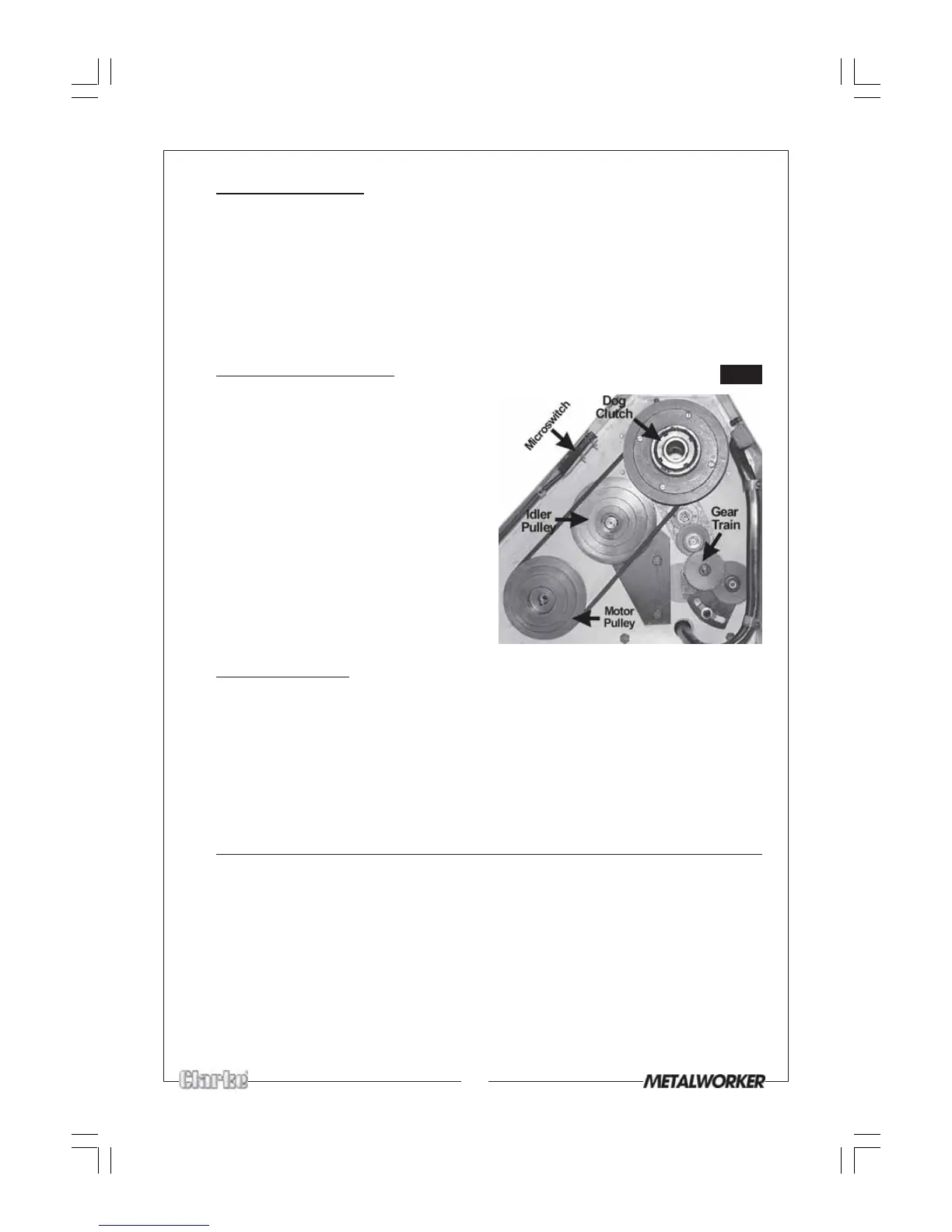
THE RUNNING GEAR - RE: FIG. 14
The running gear is protected by a cover,
the door of which must always be in place.
A microswitch is activated when the door
is opened, preventing the machine from
operating.
Drive is transmitted to the spindle via drive
belts, and to the leadscrew via a gear train.
The methods of changing gears in order
to provide different feed rates are
described on pages 21 and 22.
Drive is also transmitted to the Mill Head
by operating a Dog Clutch, shown in Fig.14.
Pushing IN drives the Mill Head, pulling OUT
drives the lathe spindle.
THE TAILSTOCK
The Tailstock may be moved along the bed to any desired position and is secured
using the lever on its side. The Tailstock spindle is provided with an internal No.3
Morse Taper for use with the Centre provided, A Revolving Centre and Drill Chuck
are also available from your Clarke dealer. (See Accessories on page 26).
It is also possible to remove the Tailstock completely, which may be necessary for
milling large pieces. Take great care, when doing so, the retain the ‘Jib Strip’ which
will drop away on removal. This is discussed on page 24.
THE SADDLE - incorporating the Cross Slide and Compound Slide
The Saddle carries the Cross-Slide on to which is mounted the Compound Slide with Tool
Post. It may be driven by the Leadscrew to provide automatic feed when the Auto Feed
lever is operated.
The position of the tool is effected by turning the cross-slide feed handle which
moves it across the bed and the saddle feed handle, which moves it longitudinally.
Additionally the compound slide feed handle may be used to move the tool by
small amounts at right angles to the cross-slide, allowing intricate and delicate
operations to be performed. The slide may also be set at an angle to the cross-slide
so that short tapers or bevels may be cut. This is described in greater detail under
‘Bevel Cutting’ on page 19.
Fig.14