Do you have a question about the Clarke MetalWorker CL300M and is the answer not in the manual?
Details CLARKE product guarantee terms, conditions, and exclusions.
Guidelines for maintaining a safe and clean workspace.
Precautions for safe use of electrical components and connections.
Advice on operator alertness, common sense, and avoiding fatigue.
Guidance on using the correct tools and not forcing the machine.
Emphasizes wearing PPE, avoiding distractions, and keeping clear of moving parts.
Instructions on cable positioning, indoor use, repairs, and adult supervision.
Specific safety measures for operating metal lathes.
Explains common safety symbols found on the machine.
Policy on recycling and environmentally sound disposal of waste.
Detailed instructions for safely connecting the lathe to the mains supply.
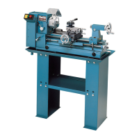
Illustrates and labels the main components of the metal lathe.
Details the headstock's drive system, spindle, and chuck mounting.
Explains the function of the running gear and its connection to the leadscrew.
Describes the tailstock's movement, securing, and spindle taper.
Outlines the saddle's role, its mounted components, and feed handles.
Details the motor, brush replacement, and overload indicator functions.
Instructions for unpacking, checking parts, cleaning, and initial assembly.
Guidance on selecting a workbench and securely mounting the lathe.
Step-by-step procedure for the first power-on and testing in low range.
Instructions for safely starting the lathe for regular operation.
Guidelines for setting up and performing basic turning operations.
Details on setting cutting tool height, workpiece mounting, and depth of cut.
Instructions for using the automatic feed for turning operations.
Explains how to set up the compound slide for cutting bevels.
Introduces screwcutting and general precautions for this operation.
Details on thread production, tool profile, metric kits, and thread dial indicator.
Explains using the dial indicator for precise thread engagement.
Explains how gear ratios affect thread pitch and how to change gears.
Provides gear configurations for normal turning and screwcutting.
Details gear settings for specific Imperial thread pitches (TPI).
Step-by-step guide to physically changing the gears on the lathe.
Pre-operation checks, lubrication, and inspection for damage.
Procedures for cleaning, oiling, and storing the lathe after operation.
Instructions for checking and replacing motor brushes.
How to adjust the cross-slide jib strip for smooth movement.
Troubleshooting stiffness in the cross-slide feed handle.
Explains how to adjust the compound slide for precision.
Lists optional accessories that enhance the lathe's functionality.
Instructions on how to change and install external jaws.
Illustrates and describes the use of fixed and moving steadies.
Comprehensive list of all parts with their corresponding numbers and quantities.
Continues the detailed listing of all lathe components.
Further listing of parts and their quantities.
Exploded diagram showing the arrangement of all components.
Technical details of the lathe, including dimensions, power, and capabilities.
Illustrates the electrical connections and circuitry of the lathe.
Official document stating compliance with relevant directives and standards.