10
Parts & Service: 020 8988 7400 / E-mail: Parts@clarkeinternational.com or Service@clarkeinternational.com
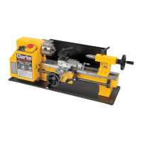
PARTS IDENTIFICATION
THE HEADSTOCK
The motor provides a direct drive to the Spindle via an internal tooth type belt.
Spindle speed is variable and is regulated by the Speed Control Knob (23),
located on the main control panel.
The spindle is provided with an internal No.3 Morse taper to accommodate a
centre for use with a face plate or turning clamp, (See ‘Accessories’ on page
30).
The Chuck Guard (3), is an essential component and is mounted on a pin
which is secured to the headstock by two screws. This should always be in
place when using a chuck.
The 3-Jaw, Self Centering Chuck (4) is mounted on the Spindle Flange (2). To
remove the chuck, simply remove the three securing nuts to the rear of the
flange allowing it to be pulled free together with the three mounting studs.
Three external jaws are also supplied which extend the capacity of the chuck.
Their uses and method of assembly is described under ‘Accessories’ on page
30.
The spindle has 6 holes drilled in its flange to accommodate a range of fixtures
such as a Face Plate, 4-Jaw chuck etc, (See ‘Accessories’ on page 30).
1 Headstock 15 Automatic Feed Lever
2 Spindle Flange 16 Cross-Slide Feed Handle
3Chuck Guard 17Apron
4 3-Jaw Chuck 18 Manual (Saddle) Feed Handle
5 Tool Post 19 Leadscrew
6 Cross-Slide 20 Motor Brush Cap
7 Compound Slide 21 Thread Dial Indicator Table
8 Tailstock Centre 22 Running Gear Cover
9 Tailstock 23 Variable Speed Control Knob
10 Tailstock Securing Nut 24 Forward/Off/Reverse Switch
11 Bed 25 Emergency Stop Switch
12 R.H. Leadscrew Bearing 26 High/Low Speed Range Lever
13 Compound Slide Feed Handle 27 Leadscrew Fwd/Neutral/Reverse
Lever
14 Thread Dial Indicator 28 Overload indicator

 Loading...