14
Parts & Service: 020 8988 7400 / E-mail: Parts@clarkeinternational.com or Service@clarkeinternational.com
The hinged transparent chuck guard is supplied loose and must be fitted to
the headstock body using the screws provided.
The four rubber feet are attached to the underside of the bed using the four
M6 pan head screws in the tapped holes provided. These screws are also used
to secure the collecting tray. We strongly recommend however, that to
provide maximum stability and additional safety, you secure the lathe to a
firm foundation as described under ‘Mounting the Lathe’.
The three external jaws for the 3-jaw self centering chuck, extend the capacity
of the chuck and are discussed in greater detail under ‘Accessories’ on page
30.
MOUNTING THE LATHE
The lathe should be mounted on a strong, heavy workbench of sufficient
height so that you do not need to bend your back to perform normal
operations. Take the necessary precautions when moving the lathe
considering its’ weight. Assistance will be required.
Ensure the location is adequately lit and that you will not be working in your
own shadow.
We strongly recommend that the machine is bolted firmly to a strong
workbench using the tapped holes used to secure the feet to the lathe. This is
to provide added stability and therefore additional safety.
To do this, remove the four M6 screws which secure the rubber feet and
collection tray to the machine (if already fitted) and discard the feet.
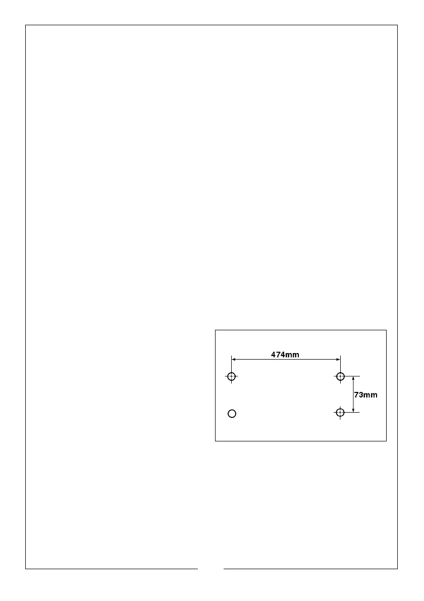
Drill four M6 clearance holes in a
worktop, at the dimensions shown in
the diagram, and with appropriate
length M6 bolts, or screws with flat
washers, (not supplied), secure the
lathe to the worktop ensuring the
collection tray is in place.
Alternatively, if you do not want a
permanent installation, you may
secure the lathe to a 5/8” thick
plywood board with a minimum recommended dimension of 800 x 300mm,
the mounting holes being centralised on the board.
When the lathe is in use the board should be clamped to workbench using
‘G’ clamps.
 Loading...