11
Parts & Service: 020 8988 7400 / E-mail: Parts@clarkeinternational.com or Service@clarkeinternational.com
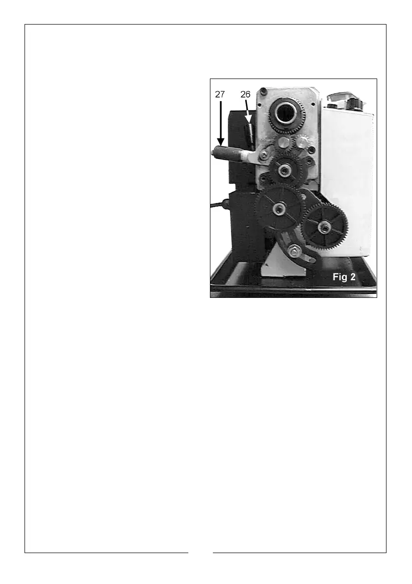
THE RUNNING GEAR
The Running Gear is protected by a cover (22), which is removed by
unscrewing the two securing hex screws.
The gear train is shown in Fig. 2. It
transmits drive to the lead screw
which acts as a worm gear and by
operating the Auto Feed Lever (15),
which engages a nut with the lead
screw (worm), drive is transmitted to
the saddle and consequently the
cutting tool. This provides a power
feed for screw cutting or general
turning operations.
The rotational speed of the lead
screw and hence the rate of feed of
the cutting tool, is determined by the
gear configuration. This is explained in
greater detail under ‘Screwcutting’
on page 20.
The drive to the leadscrew may be
disconnected by operating the lever
(27), which is also used to drive the
leadscrew in a forward or reverse
direction. (These actions are described in greater detail under ‘Screwcutting’
on page 20.
THE TAILSTOCK
The Tailstock (9), may be moved along the bed to any desired position and is
secured in position by a single nut (10), at its base. The Tailstock Spindle carries
an internal No.2 Morse taper for use with the Centre (8) provided.
A Revolving Centre and Drill Chuck are also available from your Clarke dealer.
(See Accessories on page 30).
THE SADDLE
The Saddle carries the Cross-Slide (6), on to which is mounted the Compound
Slide (7) with Tool Post (5), allowing intricate and delicate operations to be
performed. It may be driven by the Leadscrew, via a Drive Nut, to provide
automatic feed when the Auto Feed lever (15), mounted on the Apron (17), is
operated.
The position of the tool is effected by turning the cross-slide feed handle (16),
which moves it across the lathe and the saddle or manual feed handle (18),
which moves it longitudinally.
 Loading...