31
Parts & Service: 020 8988 7400 / E-mail: Parts@clarkeinternational.com or Service@clarkeinternational.com
Replace them with the external jaws,
noting the following.
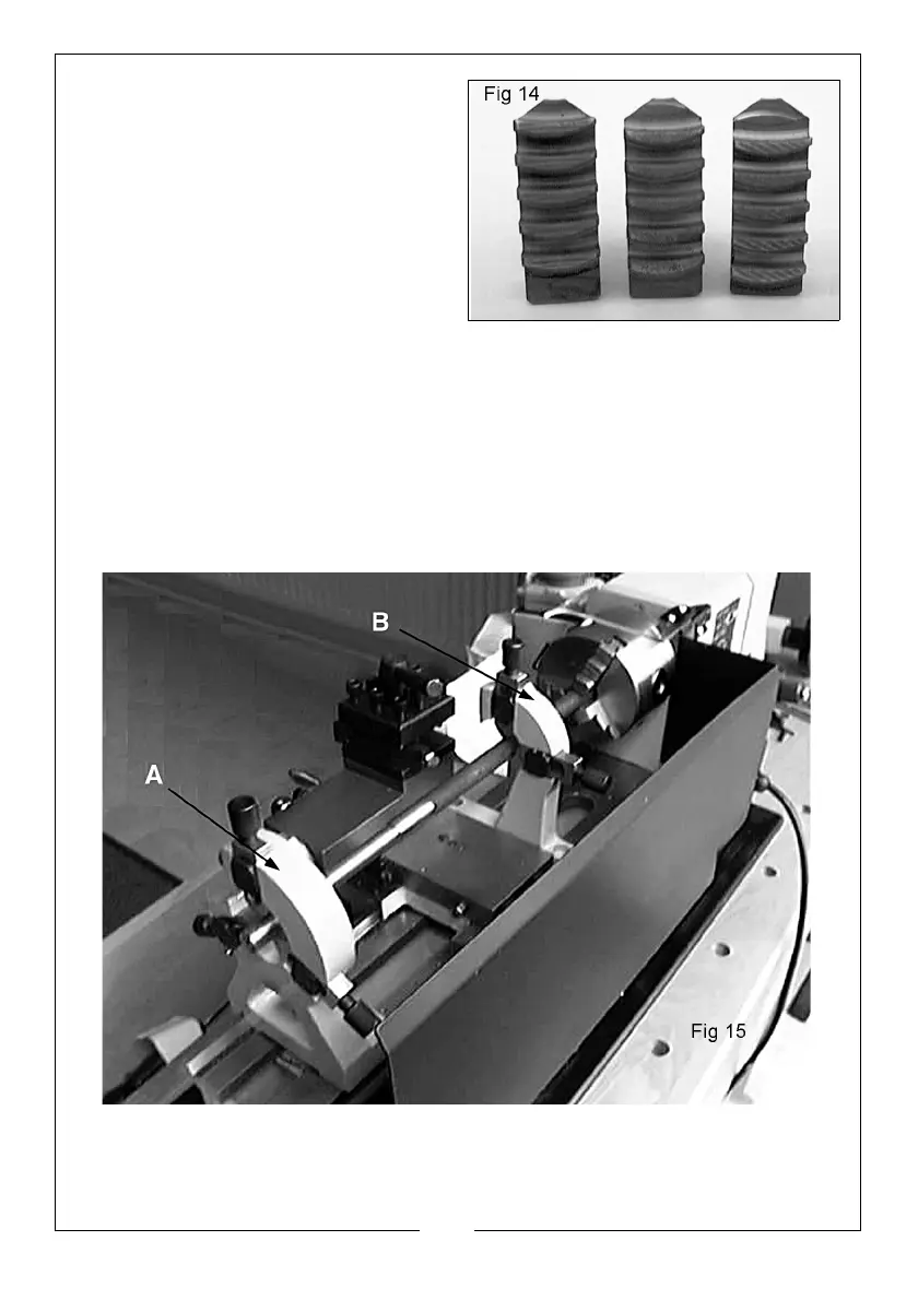
The thread segments of the jaws are
progressively ‘stepped’ as shown in fig
14. They are also numbered 1 to 3. This
is to take into account the lead of the
screw thread within the chuck. It is
therefore necessary to assemble the
jaws in the correct order.
Place them as shown in fig 14 and
assemble in the same order, clockwise in the slots in the chuck, turning the
chuck key as you insert them. Close the jaws fully and check to ensure they all
meet at the centre. If a jaw is out, open the jaws fully and retain pressure on
the jaw in question whist turning the chuck key until it snaps down into position.
Re-check to ensure all jaws meet at the centre.
FIXED AND MOVING STEADIES
Fig 15, illustrates the Fixed Steady (A) and Moving Steady (B) assembled to the
lathe, used to support a long workpiece.
 Loading...